11
2.1 CONNECTIONS
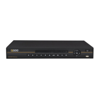
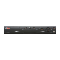
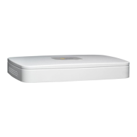
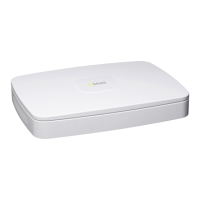
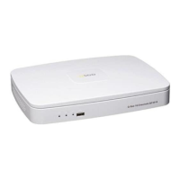
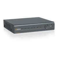
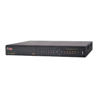
The illustrations below show the ports found on the back of your DVR. Their location will differ by model,
but their function will be the same. The Connections and Specifications sheet that came with your
recorder will show the layout of your recorder’s connectors along with any extra information that may
apply to your model.
VGA
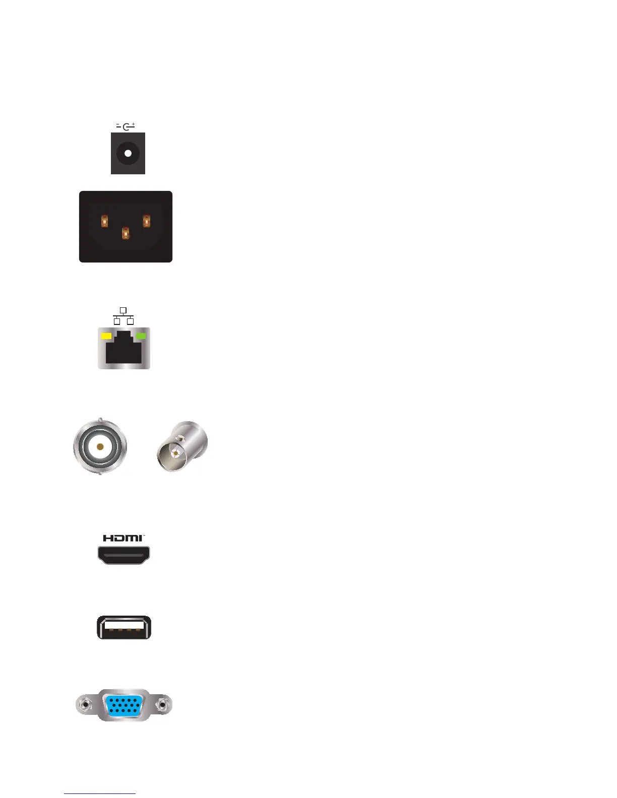
POWER
Your DVR will have either a small port (top) or a larger, more
conventional power port (below). DVRs with the smaller port will have a
power adapter as part of the power cord while those larger power port
have an internal power supply.
NETWORK PORT
Use this single Ethernet port to connect your DVR to your network
router.
VIDEO IN PORTS
The yellow end of the camera extention cable connects to these ports.
While they use identical cables, neither conventional analog nor SDI
cameras will work with your AnalogHD system.
HDMI
Use the included HDMI cable to connect to a high-definition video
display.
USB
Depending on the model of your DVR, these ports may be located on
both the front and back panels. Connect your USB mouse to one of
the ports on the back panel, leaving the other port available for use in
backing up files.
VGA
For connecting your DVR to a VGA computer monitor. VGA cable not
included.
 Loading...