Q5X USER MANUAL: QT-AD10 TRANSMITTER FAMILY JUNE 2020
___________________________________________________________________________________
___________________________________________________________________________________
For an updated copy of this document, visit www.Q5X.com/support 10 | Page
8.0 APPENDIX – DIAGRAMS & QUICK START GUIDES
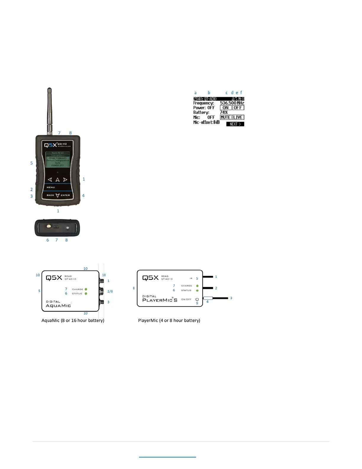
8.1 MICCOMMANDER DIAGRAMS
KEY:
1 Navigation arrows
2 MENU button – Open special menu when available
3 BACK button – Return to previous menu
4 ENTER button - Select item
5 LCD Display
6 2.4 GHz Antenna connector
7 Micro USB input
8 On/Off button, with LED heartbeat Indicator
a Transmitter Serial Number
b Transmitter Name
c Encryption
d Linking Status
e 2.4GHz RSSI
f Message que
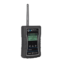
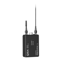
8.2 TRANSMITTER DIAGRAMS
Common features:
1 2.4 G antenna For the RCAS control channel.
2 Audio input Connects to a microphone with a special Lemo connector.
3 UHF antenna For RF signal transmission.
4 Serial number Unique serial number for RCAS identification and control on the antenna. (Back of the AquaMic.)
5 IR port Infrared sync with the receiver for set-up, initiating encryption and installing firmware updates.
6 Status LED See user manual for details on LED patterns and colours.
7 Charge LED Red = charging, green= charged and flashing red/green = error.
8 USB Port Charges the battery. (AquaMic charges through the same connector as the audio input.)
Unique features:
9. On/Off button Manual power control between on, standby and storage modes. (Not part of the AquaMics.)
10. Belt clip holes Allows vertical and horizontal placement. (Not part of the PlayerMics.)