Manual for Advance 6T series
Installation Instruction
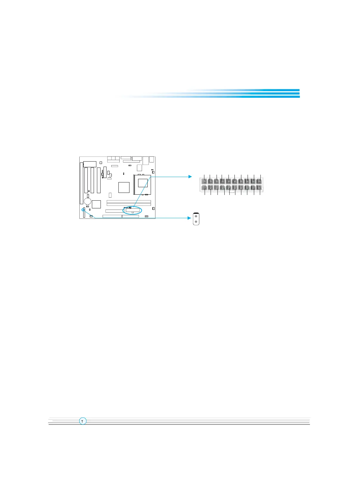
ATX Power Supply Connector & Power Switch( POWER SW )
Be sure to connect the power supply plug to this connector in its proper orientation. The
power switch ( POWER SW ) should be connected to a momentary switch (power button).
When powering up your system, first turn on the mechanical switch of the power supply (if
one is provided), then push once the power button. When powering off the system, you
neednt turn off the mechanical switch, just
Push once
*
the power button.
Note: * If you change “soft-off by PWRBTN” from default “Instant-off” to “Delay 4
Sec” in the “POWER MANAGEMENT SETUP” section of the BIOS, the power button
should be pressed for more than 4 seconds before the system powers down.
Hard Disk LED Connector (HD_ LED)
The connector connects to the cases IDE indicator LED indicating the activity status of IDE
hard disk. The connector has an orientation. If one way doesnt work, try the other way.
Reset Switch (RESET)
The connector connects to the cases reset switch. Press the switch once, the system
resets.
Speaker Connector (SPEAKER)
The connector can be connected to the speaker on the case.
Power LED Connector (PWR_LED)
When the system is in S0( full-on ) status, the LED is on. When the system is in S1( suspend)
status, the LED is blink. When the system is in S4( STD ) or S5( soft-off ) status, the LED is
off. The connector has an orientation.
ACPI LED Connector (ACPI LED)
The ACPI LED is a double-color light with three pins. Pin1and Pin2 drive different color lights.
If Pin1 drives the orange light , then, Pin2 drives the green light, the following status will
come out. When the system is in S0 status, the LED is green on. When the system is in S1
status, the LED is green blink. When the system is in S4 or S5 status, the LED is off.
POWER SW
ATX Power Supply Connector
3.3V -12V GND PSON GND GND GND -5V 5V 5V
3.3V 3.3V GND 5V GND 5V GND PW-OK 5VSB 12V
 Loading...