Atmospheric Oil Mist Detection System
MULTIPLEX
AM8/JANUARY 2015
EMAIL qmi@oilmist.com WEBSITE www.oilmist.com 4 East Barnet Road, London, England, EN4 8RW TEL +44 (0)20 7328 3121
Introduction Part1-7
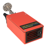
DESCRIPTION OF SENSORS (Q10)
See photo Part 1-8
The Sensor operates using the principle of light scatter (nephelometry). The power
and signal are transmitted to and from the Monitor through a single cable sending a
timed analogue signal. All Sensors sample simultaneously and continuously every half-
second (500 milliseconds).
The assembled Sensor comprises:
(a) Articulated Joint and mounting flange
(b) Chamber
a) ARTICULATED JOINT AND MOUNTING FLANGE
See drawing Part 1-9
The Articulated Joint is fitted to bulkhead or deckhead allowing the Sensor to be
positioned facing the flow of air in the chamber being monitored.
The sub-assembly is fitted to the Articulated Joint by 4 screws, which can be removed
if and when the Sensor lens requires cleaning.
b) CHAMBER
Inside the unit are the PCB, integral fan, and sensing lenses. Power is supplied to the
12V fan by a single cable, which is connected to the Monitor (or to a Junction Box).
The fan draws the sample of air past the sensors through the outlet ports.
In the front of the Sensor unit are the air intake louvers, and an LED, which shows
green when the fan is working. The electronics are mounted on the back of the chamber
casing and are protected by the cover sealed to IP65.
At the back of the unit is the multi-purpose power and signal socket. Next to the socket
is the mounting spigot.
NOTE: The integral fan is interchangeable without recalibrating the Sensor.