Table of Contents
PART 1
INTRODUCTION
Technical Specifications Part1-2
QMI MULTIPLEX Monitor Part1-3
MULTIPLEX Central Monitor Unit (CMU) Layout Part1-4
Description of Central Monitoring Unit (CMU) Part1-5
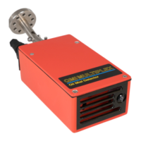
Description of Sensor (Q10) Part1-7
Photograph of Sensor (Q10) Part1-8
Drawing of Atmopheric Sensor Part1-9
PART 2
INSTALLATION
General Wiring Layout for MULTIPLEX Atmospheric System Part2-2
Cut out for QMI Panel/Wall Mounted Monitor Part2-3
Positioning and Location of Sensors Part2-4
Positioning of QMI Atmospheric Sensor (Q10) Part2-5
Schematic of Positioning of Sensor and Best Practice Part2-7
Monitor with Harting Connectors Part2-9
Cable Specifications Part2-10
Wiring Description Part2-11
Wiring of Socket Part2-12
Multi-core Cable Sizing Table When Less than 10 Atmospheric
Sensors are used Part2-13
Multi-way Junction Box PCB with 12V PSU (Q07) Part2-14
Connector (Q01H1) Details for QMI MULTIPLEX CMU - Junction Box Part2-15
Cable Details for Atmospheric Sensors 6 Pole Socket (Q1006) Part2-16
Connector Details for QMI MULTIPLEX CMU - Junction Box when
used with Atmospheric Sensors (Q10) Part2-18
Wiring Details for Junction Box to Atmospheric Sensors (Q10) Part2-19
Overall View of Connector No. 4 For QMI MULTIPLEX Mains
110/240V Power Socket (Q01H4) Part2-20
110/240V Power Supply Wiring Part2-21
Cable Details for QMI MULTIPLEX Relay Alarm Output (Q01H3) Part2-22
Cable Details for QMI MULTIPLEX Relay Shutdown Output (Q01H2) Part2-23
Alarm Output Wiring Part2-25
Optional Plant Shutdown Wiring Part2-26
Graph to show relationship between mg/L, Digital Readout of
Percentage of Alarm Level and the Percentage of LEL Part2-27
QMI MULTIPLEX 4-20mA Data Logger Output Part2-28
Cable Details for QMI MULTIPLEX 4-20mA Data Logger Output
(Q01H5) Part2-29