Atmospheric Oil Mist Detection System
MULTIPLEX
AM8/JANUARY 2015
EMAIL qmi@oilmist.com WEBSITE www.oilmist.com 4 East Barnet Road, London, England, EN4 8RW TEL +44 (0)20 7328 3121
Installation Part2-13
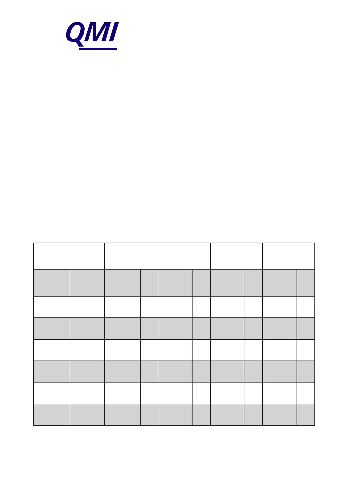
MULTI-CORE CABLE SIZING TABLE WHEN LESS THAN
10 ATMOSPHERIC SENSORS ARE USED
It is not necessary to use a 19 twisted pair cable between the CMU and the Multi-
way Junction Box if less than 10 Sensors are installed.
Below is a chart on how to select a multi-core cable. If fewer Sensors are to be used
the terminals to be wired in the Junction Box are as follows:
- drain connection (31) must always be used
- supply common (25) is used when only 3 or 4 Sensors are used
- supply common (25 & 26) are used when more than 3 or 4 Sensors are used
- supply + (27) is used when only 3 or 4 Sensors are used
- supply + (27 & 28) is used when more than 4 Sensors are used
- fan failure connections (29 & 30) are always used
- 12V Fan Failure connection (32) is always used
NOTE: For further wiring details turn to Part 2-16.
Numbers (25) to (32) refer to terminals.
25 & 26
Supply
Common
27 & 28
Supply
+
29 & 30 Fan
Failure
32
12V Fan
Failure
No of
Sensors
No of
Twisted
Pairs
Wire No. Pair
No.
Wire No. Pair
No.
Wire No. Pair
No.
Wire No. Pair
No.
3 7 7 & 8 4 9 & 10 5 11 & 12 6 13 & 14 7
4 8 9 & 10 5 11 & 12 6 13 & 14 7 15 & 16 8
6 12 13 & 14
15 & 16
7
8
17 & 18
19 & 20
9
10
21 & 22 11 23 & 24 12
7 13 15 & 16
17 & 18
8
9
19 & 20
21 & 22
10
11
23 & 24 12 25 & 26 13
8 14 17 & 18
19 & 20
9
10
21 & 22
23 & 24
11
12
25 & 26 13 27 & 28 14
9 15 19 & 20
21 & 22
10
11
23 & 24
25 & 26
12
13
27 & 28 14 29 & 30 15