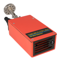
Atmospheric Oil Mist Detection System
MULTIPLEX
AM8/JANUARY 2015
EMAIL qmi@oilmist.com WEBSITE www.oilmist.com 4 East Barnet Road, London, England, EN4 8RW TEL +44 (0)20 7328 3121
Introduction Part1-3
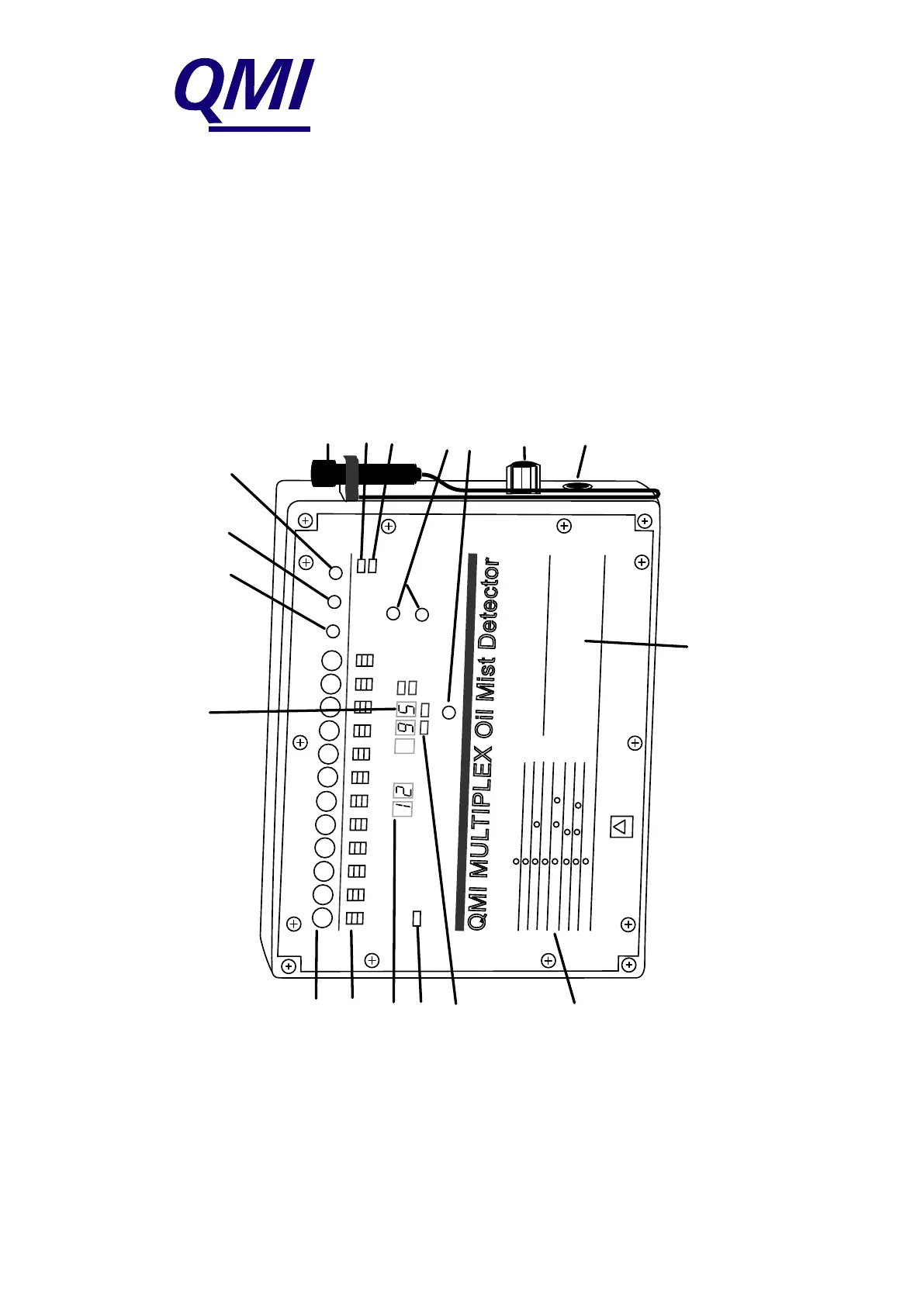
Channel switches
Oil mist status LED and
Alarm indicator
Channel identification
Power indicator
Setting indicator LEDs
Operating instructions
Magnetic pen
Testing
CPU indicator
Alarm setting switches
Alarm level viewing switch
Fuse (FS3 - Q0115)
Security key switch
1
2
3
4
5
6
7
8
9
10
11
12
!
Oil mist level reading, setting and fault location read out
Fault directory
Isolate, reset and test switches
Channel number
Channel
Reading
mgm/litre
Isolate
Reset
Test
Testing
No CPU
Raise alarm level
Lower alarm level
OPERATING INSTRUCTIONS
To display a function, place
Magnet Pen FLAT over specified circle
Function
Circle
Channel level reading (%)
Pre-set alarm level (mgm/litre)
Self-test programme
Detector alarm test
Isolate detector
Restore detector
Normal operation
Channel number
Alarm level +
Channel number
Test
Alarm leve
l + Test + Channel number
Isolate + Channel number
Isolate + Reset + Channel number
Reset
Quality Monitoring Instruments, London, NW6 2HL, UK
FAULT DIRECTORY
Channel Reading Fault Condition Action required
1-12 F1 Cable fault Check/repair relevant cable
1-12 F2 Detector dirty
Clean detector according to instructions
1-12 F3 Detector faulty Clean as F2 first or replace detector
1-12 IC Isolated Circuit Checking operating instructions
C F4 Fan Failure Check fan and fan failure detecting system
NOTE: if 'No CPU' light is on, refer to manual.
'dd' on test is dirty
detector.
'cd' on test is clean detector.
Alarm level
Setting
%
QMI MULTIPLEX MONITOR