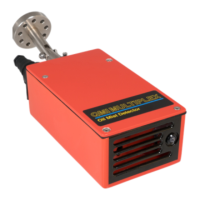
Atmospheric Oil Mist Detection System
MULTIPLEX
AM8/JANUARY 2015
EMAIL qmi@oilmist.com WEBSITE www.oilmist.com 4 East Barnet Road, London, England, EN4 8RW TEL +44 (0)20 7328 3121
Running Procedure Part3-7
CHANGING THE NUMBER OF SENSORS
Setting up the QMI MULTIPLEX System CMU for a different number of Sensors.
The QMI MULTIPLEX can have a total of 12 Sensors plugged into it. The display will show 12
positions illuminated.
The number of Sensors in use can be adjusted by switches located on the back of the MP12
PCB v 3.2.
There is a 10 way Binary switch located on MP12 PCB v 3.2. Switches 1 to 4 are for the
number of Sensors to be set up.
Switches 1-4 are for the number of Sensors to be set up.
Sensors required Switch 1 Switch 2 Switch 3 Switch 4
01 on off off off
02 off on off off
03 on on off off
04 off off on off
05 on off on off
06 off on on off
07 on on on off
08 off off off on
09 on off off on
10 off on off on
11 on on off on
12 off off on on
Switch 5 is for the oil mist range.
With Switch 5 set to OFF the range is from 0 up to 1.30mg/L
With Switch 5 set to ON the range is from 0 up to 2.00mg/L
After changing the set Switch from OFF to ON or ON to OFF, the alarm levels should be
adjusted for each channel.
Switch 6 should always be set to OFF.
Switch 7 should always be set to OFF.
Switch 8 should always be set to OFF.
Switch 9 is for Channel selection display.
Switch 9 is set to OFF the Monitor display will show Channels 1-12.
Switch 9 is set to ON the Monitor display will show Channels 13-24.
If a change is made to Switch 9, the Monitor will need to be reset by placing the magnetic
pen over the reset circle, or turning the key a quarter turn, and then back.
Switch 10 should always be set to OFF.