3. Display elements
The kit uses a 2 row, 16 character LCD module, with black text on a yellow/green background.
There is a backlight which can be switched off if desired, to save a few mA of current
consumption. The display has a large, easy to read font, and is perfectly readable in bright sunlight
with no backlight.
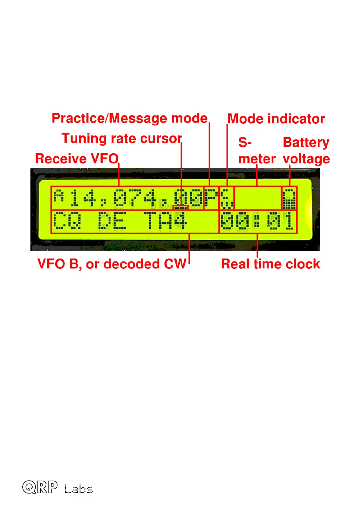
The main display layout during ordinary operation (which will be called “main operating mode”) is
shown in the following photograph. The display during beacon or message transmission modes,
menu editing, alignment etc. differs. The main display elements are as follows:
The receive VFO frequency is always displayed, to 10Hz resolution, at the top left. This
may be VFO A or VFO B. In CW mode the nominally 700Hz CW offset is automatically
applied. Ordinarily in CW mode, the displayed frequency is also used for transmission.
Tuning rate cursor: the underline appears under the digit which is currently tuned by the
rotary encoder. In this example, the tuning rate is 100Hz per click, because the cursor is
under the 100Hz digit.
Practice mode: when in CW practice mode (actual transmitting disabled), a ‘P’ is displayed
to the right of the frequency on the top row. If the practice mode was caused automatically
as a self-protection, by plugging in the GPS, a ‘G’ is displayed. During saved message
transmissions, this character is set to ‘M’ and in ordinary operation, it is blank.
Mode indicator: this single character indicates the current operating mode of the tranceiver;
in the example in this photograph it is “CW”.
S-meter: these 3 characters are configurable and display the S-meter/SWR/Power meter.
Battery voltage: a battery icon appears to indicate the battery voltage in 7 user-definable
steps: from full to empty and 5 steps in between. It may also be shown or hidden.
Transmit VFO: in SPLIT mode, the transmit VFO is displayed on the bottom row of the
display.
RIT (Receiver Incremental Tuning): when not in SPLIT mode, and when the RIT is non-
zero, the RIT value is displayed in the bottom left (where the photo shows the VFO B
frequency). When RIT is non-zero, and when not in SPLIT mode, the reception frequency is
the transmit VFO frequency (which may be VFO A or B) plus the RIT (which may be a
negative offset).
QMX operang manual; rmware 1_00_012 10
 Loading...

