Note that the QMX cannot supply +5V to the GPS module power supply, and in this regard the
GPS interface differs from that of the QRP Labs QCX-series transceivers. So you need to arrange
a separate 5V power supply for the QLG2 GPS (for example).
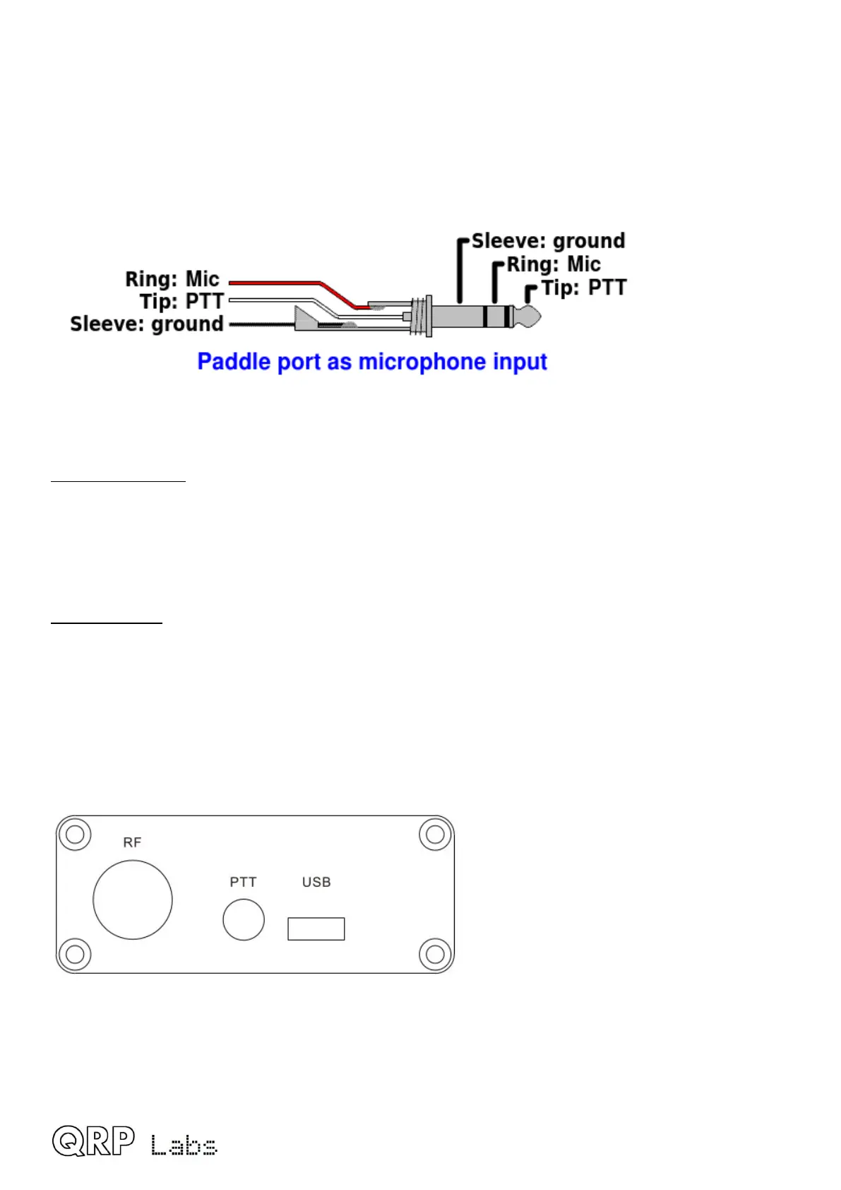
3). Microphone interface
In SSB mode, an electret microphone and PTT switch may be connected to the Paddle port.
An internal +2.2K pullup to +3.3V is provided to power electret microphones.
Audio connector
The audio output connector is a standard 3.5mm stereo jack socket for connecting 32-ohm
earphones or similar. It is not suitable for driving a loudspeaker directly. QMX internally controls
the Left and Right channels separately which makes future interesting functionality possible.
DC connector
The DC connector is a 2.1mm barrel jack connector, the same as used on other QRP Labs
transceiver kits such as QCX+, QCX-mini and QDX.
The center pin is positive, the barrel is ground.
The supply voltage range for QMX is 6.0 to 12.0V. Maximum power output depends on the supply
voltage.
This is the QMX right panel.
QMX operang manual; rmware 1_00_012 8

 Loading...
