35
Test Procedures:
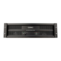
Model 3800
1. Inspection
a. Carefully inspect the amplifier module for burned or damaged components.
2. Hook-up
a. Connect load resistors, oscilloscope channel A (20V/Div.), and distortion analyzer (1000
Watt/0.1% input/distortion) to the amplifier output. Note: the output may be measured before
the relay at the center tap (pins 7 and 8 of the 8-pin connector)
b. Connect the analyzer’s distortion output to channel B of the oscilloscope (0.1V/Div.)
c. Set the analyzer signal output to 2kHz, 1.25V RMS. Make all signal level changes with the
amplifier gain controls after this adjustment is completed.
d. Connect the Variac (set to 0) to the amplifier’s AC inlet receptacle.
Note: Do not connect the telephone mod signal connector at this point.
The following instructions are for 120 V models. For 240 V models, expect half the AC current draw
at twice the AC voltage with respect to the AC measurements given.
3. Initial start-up
a. Disconnect the load resistors from the amplifier.
b. Turn the amplifier on and slowly increase the Variac setting to 120VAC. Watch the 5 amp
current meter for excessive current draw (more than 0.4 amps). The power/protect LED should
come on red at about 20VAC. At approximately 100VAC the speaker mute relay should turn on
and the power/protect LED should turn green.
c. Install the input mod connector. Observe the output for symmetrical waveform; the distortion
analyzer should indicate less than 0.05% distortion. The signal level on the oscilloscope should
read 160V
P-P
(400W) when set in accordance with the above procedure (step 2c.). This verifies
correct overall channel gain. Characteristic step spikes should be visible on the positive and
negative halves of the waveform (still into no load) on channel B of the oscilloscope.
d. Switch the load to 8 ohms and vary the amplifier gain just above and below the step switching
level. Watch for obvious step oscillation. This test must be done when the amplifier channel is
cold since any tendency to instability will disappear as the amplifier warms up. You may
experience a severe glitch on the negative step, which can be corrected by barely turning up
the crossover trimmer. Verify that positive and negative peaks go into step switching within 3
volts peak of each other.
e. Move the wiring harness and tap the circuit boards with a non-conductive implement such as
the handle of a small screwdriver and watch the scope output and distortion trace for
intermittency. Remove the 8-ohm load.
4. DC protect
a. Check that there is no load on the output of the amplifier. Use a jumper to short pin 8 (+) of the
IC to ground; the relay must turn off and the power/protect LED must turn red immediately
(within 0.1 second). The amp should return to normal operation 2 to 3 seconds after removing
the short.
b. Short pin 4 (-) of the IC to ground; the relay must turn off and the power/protect LED must turn
red immediately (within 0.1 second). The amp should return to normal operation 2 to 3 seconds
after removing the short.
5. Signal indicators
a. With a 2kHz input signal, adjust the amp gain to obtain 50W of output power. The two yellow
LEDs should be on at this point; the –6dB LED may be dimly lit.
b. Attenuate the signal by 10dB. The –6dB LED should be off.
c. Attenuate the signal by 20dB. The –6dB LED should be off and the –30dB LED should be dimly
lit.
6. 4 ohm power output and frequency response
a. Switch the distortion analyzer to volts/power. Select a 2kHz signal input to the amplifier.
b. Adjust the input signal to obtain 300 watts (x2) output and observe power output at 20Hz (-
0.5dB max.), and 20kHz (-0.5dB max.).
7. Current limit adjustment
 Loading...