Do you have a question about the QSC RMX 2450 and is the answer not in the manual?
Alerts users to dangerous voltage and risk of electric shock.
Alerts users to important operating and maintenance instructions.
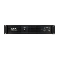
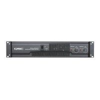
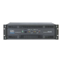
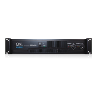
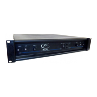
Introduces the 2-RU, fan-cooled, 2-channel RMX amps and their models.
Lists essential features of the RMX Series Amplifiers, such as clip limiters and filters.
Details the power switch, indicators, and gain controls on the front of the amplifier.
Explains the barrier strip, XLR, TRS inputs, Speakon outputs, and DIP switches.
Explains what a clip limiter is and how it functions to prevent distortion.
Provides guidance on when to enable or disable the clip limiter for different speaker types.
Describes the low-frequency (LF) filter options (30 Hz, 50 Hz, OFF) and their effects.
Explains how to use the parallel input switches for linking multiple amplifiers.
Details how to combine both amp channels for increased power into a single speaker.
Compares Stereo, Parallel Input, and Bridge Mono modes for amplifier operation.
Illustrates the connections and signal flow for the bridge mono operating mode.
Provides instructions and diagrams for mounting the amplifier in a rack.
Details XLR, TRS, and barrier strip inputs, including balanced/unbalanced configurations.
Explains the Neutrik Speakon output connectors and their usage.
Details how to connect speakers using binding post terminals.
Instructs on connecting the amplifier to the correct AC power voltage.
Covers turning the amplifier on/off and adjusting channel gain levels.
Describes the meaning of the SIGNAL and CLIP LEDs on the front panel.
Explains the cooling system and the importance of proper ventilation.
Discusses amplifier protection, internal heating, and protective muting.
Illustrates setups for mono mixing, stereo mixing, and sound reinforcement.
Depicts bi-amping configurations and biamp monitor setups.
Shows applications for instrument amplification and bi-amping.
Addresses problems when the power indicator is not lit.
Guides on troubleshooting when the signal LED lights normally but there's no sound.
Troubleshoots issues where the signal LED is not lit despite power.
Addresses problems indicated by a flashing CLIP LED when signal is applied.
Covers troubleshooting when CLIP LEDs are solid, indicating protective muting.
Diagnoses distorted sound related to CLIP LED flashing or incorrect connections.
Addresses problems with lack of channel separation and incorrect mode settings.
Guides on identifying and resolving hum in the audio signal.
Provides steps to diagnose and fix hiss from the source or amplifier.
Offers solutions for controlling squeals and feedback in audio systems.
Details the output power in watts for various impedance loads and conditions.
Lists specifications for distortion, frequency response, and noise levels.
Provides data on gain, sensitivity, impedance, controls, and indicators.
Details connectors, cooling methods, amplifier protection, and physical dimensions.
Lists power requirements, consumption figures, and notes for different operating levels.
States QSC's non-liability for damages due to negligence or improper installation.
Outlines the three-year warranty terms, coverage, and return procedures.
Provides mailing address, telephone numbers, and fax for QSC Audio Products.
Lists the company's website and email addresses for inquiries.
Details the meaning of warning symbols like lightning flash and exclamation point.
Lists crucial safety instructions for operation, installation, and maintenance.
| Power Output (8 ohms, stereo) | 450 W per channel |
|---|---|
| Power Output (8 ohms, bridged mono) | 1500 W |
| Power Output (4 ohms, bridged mono) | 2400 W |
| Frequency Response | 20 Hz - 20 kHz, +0/-1 dB |
| Weight | 44 lbs (20 kg) |
| Signal to Noise Ratio | > 100 dB |
| Total Harmonic Distortion | < 0.05% |
| Input Impedance | 10 kOhms unbalanced, 20 kOhms balanced |
| Gain | 32dB |
| Cooling | Variable speed fan |
| Connectors | XLR, 1/4" TRS inputs; binding post and Speakon outputs |
| Dimensions | 3.5" x 19" x 15.9" |
| Power Requirements | 50-60 Hz |
| Power Output (2 ohms, stereo) | 1200W |