9
EN EN
Outputs
• Wiring connections are shown on the back of the chassis.
• Binding Post Outputs
• Stereo and Parallel Mode: Wire as shown by loudspeaker symbols 1 and 2.
• Bridge Mode: Wire as shown by Bridge Mono loudspeaker symbol.
NL4 Outputs
Each channel accepts a normal 2-wire cable. In addition, Channel 1 accepts 4-wire cables for single
cable stereo or bi-amp connection.
WARNING!:
OUTPUT TERMINAL SAFETY WARNING! Do not touch output
terminals while amplifier power is on. Make all connections with amplifier
turned off. Risk of hazardous energy!
WARNING!:
Stereo and Parallel Mode- Connect each loudspeaker to its own channel of the amplifier, as shown on the
left side of the chassis label. The Mode configuration switches must be set for Stereo or Parallel Mode.
Bridge Mode- Bridge Mode configures the channel pair to drive a single audio circuit. The Mode configuration switches must be set for
Bridge Mode.
Connect the load as shown on the right side of the binding posts or to the left on Channel 1’s NL4. 4 ohms is the minimum impedance for Bridge
Mode use.
CAUTION!:
Do not use less than 4 ohm load in Bridge Mode! Note polarity of connection for Bridge Mode.
CAUTION!:
OUTPUT WIRING WARNING: CLASS 2 WIRING SHALL BE USED. FOR BRIDGED MONO MODE, CLASS 3 WIRING SHALL
BE USED.
LED Indicators
The LED indicators can be used to monitor system operation and identify common problems.
POWER: A single blue indicator, on left side of AC power switch.
Normal indication: AC switch ON: indicator
will illuminate.
If no indication: Check AC power cord and AC
outlet. Check rear panel circuit breakers.
CLIP: red
Normal indication: Illuminates whenever the
amplifier is driven beyond full power. The LED’s
brightness indicates the amount of distortion.
Distortion that causes only brief flashing may
not be audible. During muting, the indicator
fully illuminates. This occurs during normal
“On-Off” muting.
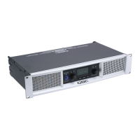
— Figure 12 —
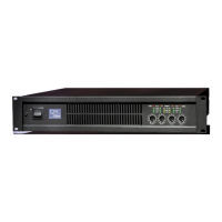
— Figure 13 —