+7(495) 797-3311 www.qtech.ru
Москва, Новозаводская ул., 18, стр. 1
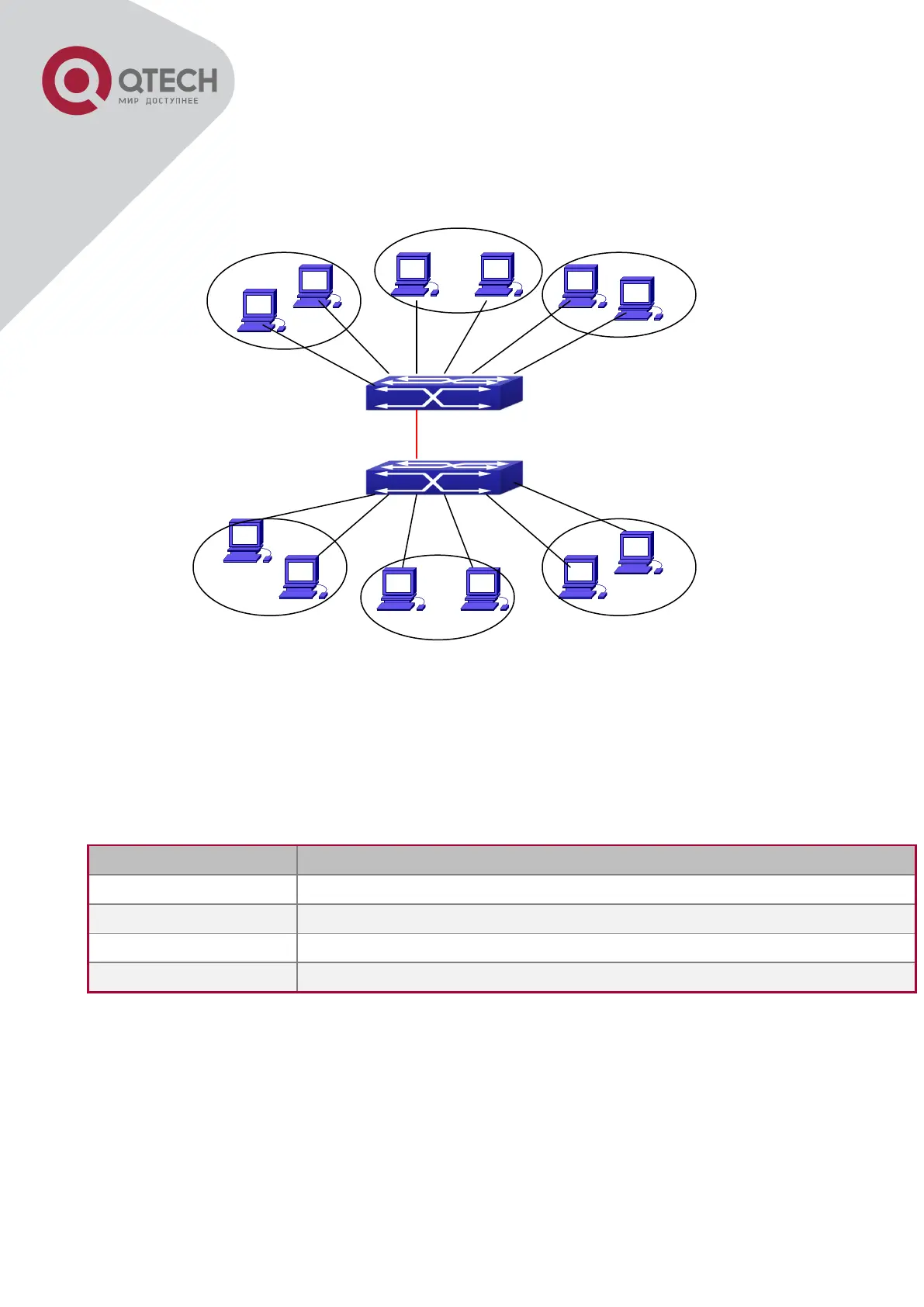
16.1.3 Typical VLAN Application
Scenario:
Typical VLAN Application Topology
The existing LAN is required to be partitioned to 3 VLANs due to security and application
requirements. The three VLANs are VLAN2, VLAN100 and VLAN200. Those three VLANs are
cross two different location A and B. One switch is placed in each site, and cross-location
requirement can be met if VLAN traffic can be transferred between the two switches.
Configuration description
Site A and site B switch port 2 -4.
Site A and site B switch port 5 -7.
Site A and site B switch port 8 -10.
Site A and site B switch port 11.
Connect the Trunk ports of both switches for a Trunk link to convey the cross-switch VLAN
traffic; connect all network devices to the other ports of corresponding VLANs.
In this example, port 1 and port 12 is spared and can be used for management port or for other
purposes.
The configuration steps are listed below:
Switch A:
Switch(config)#vlan 2
 Loading...