+7(495) 797-3311 www.qtech.ru
Москва, Новозаводская ул., 18, стр. 1
The connections among the switches are shown in the above figure. All the switches run in the
MSTP mode by default, their bridge priority, port priority and port route cost are all in the
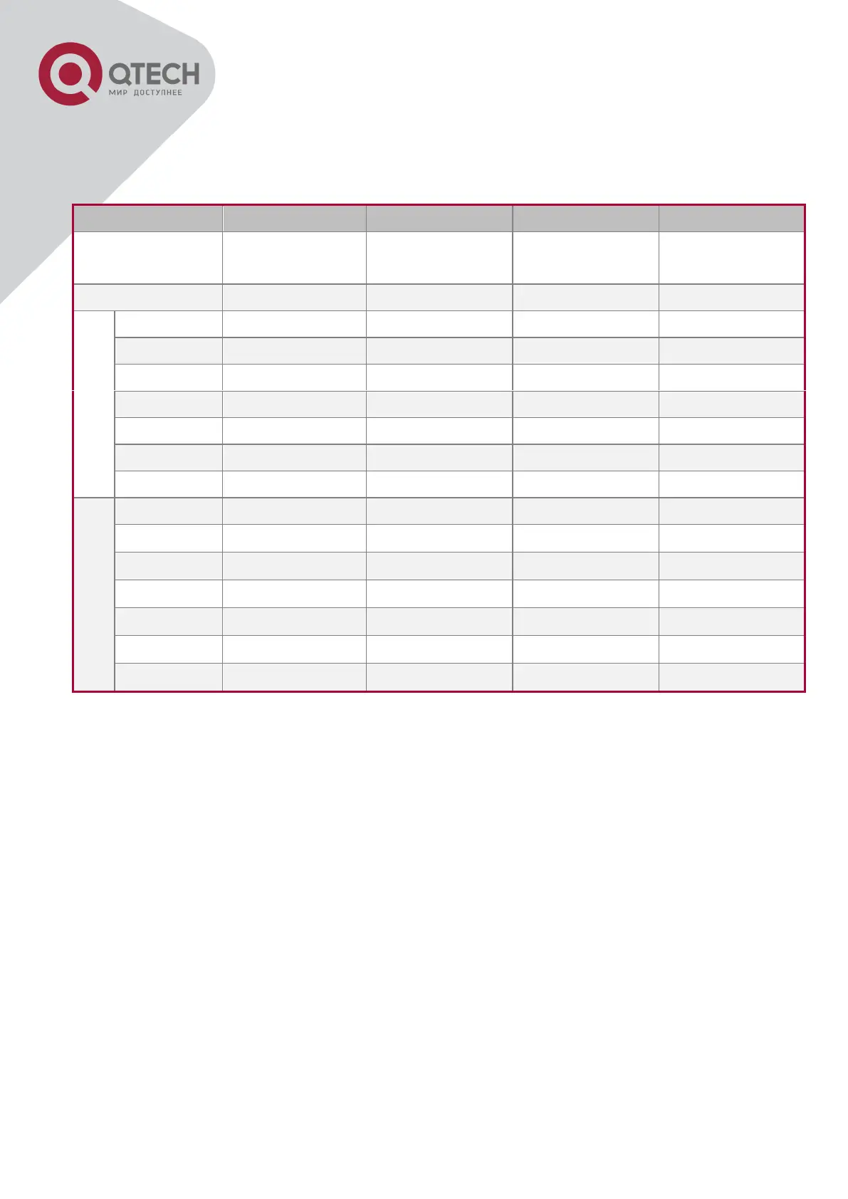
default values (equal). The default configuration for switches is listed below:
By default, the MSTP establishes a tree topology (in blue lines) rooted with SwitchA. The ports
marked with “x” are in the discarding status, and the other ports are in the forwarding status.
Configurations Steps:
Step 1: Configure port to VLAN mapping:
Create VLAN 20, 30, 40, 50 in Switch2, Switch3 and Switch4.
Set ports 1-7 as trunk ports in Switch2 Switch3 and Switch4.
Step 2: Set Switch2, Switch3 and Switch4 in the same MSTP:
Set Switch2, Switch3 and Switch4 to have the same region name as mstp.
Map VLAN 20 and VLAN 30 in Switch2, Switch3 and Switch4 to Instance 3; Map VLAN 40 and
VLAN 50 in Switch2, Switch3 and Switch4 to Instance 4.
Step 3: Set Switch3 as the root bridge of Instance 3; Set Switch4 as the root bridge of Instance
4
Set the bridge priority of Instance 3 in Switch3 as 0.
Set the bridge priority of Instance 4 in Switch4 as 0.
The detailed configuration is listed below:
 Loading...