5.0 LT-310 Control Unit Specifications
Enclosure:
Wall mounted glass-fiber reinforced polyester, IP65/NEMA4X protection for location in harsh environments.
Dimensions: 11.42” H X 9.79” W X 6.56” D (290 mm H X 249 mm W X 167 mm D)
Mounting Legs: (4) 0.50” X 0.31” (13 mm X 8 mm) Slots on 12.19” H X 6” W Centers (310 mm H X 152 mm W)
Inputs:
Discrimination between water and steam for up to 6 channels numbered in ascending order.
Sensitivity: Discrimination threshold may be selected for a minimum conductivity of 1 mS/cm², 2 mS/cm² or 4
mS/cm². (Use of a shrouded probe insert effectively reduces these values by half.)
Probe Normal State: This is set by solder jumps, making a jump for all probes anticipated to be in the wet state
as normal. Probes that are normally wet require a single wire, probes that are normally dry require two wires.
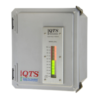
Display:
Two vertical columns having 0.4” (10 mm) square LED’s on the front of the enclosure. One row of Green LED's
represents water and another row of Red LED’s represents steam. A Yellow flashing LEDs signal a
System or Process Fault Condition.
Supply Requirements:
100 to 240 VAC ± 10%, 48 - 63 Hz
Utility Consumption:
20 Watts
Temperature Rating:
Operating: -13º F (-25º C) to 158º F (70º C), Storage: -58º F (-50º C) to 212º F (100º C)
Relay Outputs:
Alarms/Trips: RL1 through RL6 can be set to activate on the input of one probe channel, or any of three par-
ings. Enabling all three parings results in a voting logic circuit that polls three probes, activating in a 2 of 3 sce-
nario.
Fault Alarm: One relay (RL7) is dedicated to activate when a Fault is indicated.
Alarm and Trip Relays may be set to a direct (de-energized) or inverse (energized) normal state The Fault relay
is set to an inverse (energized) normal state.
Relay Ratings:
DPDT, Max. Current: 8 Amps @ 250VAC
Remote Display:
Twelve terminals are provided for direct connection to a Remote Display Unit. The Remote Display Unit option
LTI-310 duplicates the display on the front of the main unit and is intended for control room location.
Panel Mounted, 7.75” H X 3” W (197 mm H x 76 mm W), Panel cut-out: 4.2” H X 2.625” W (107 mm H x 67
mm W)
8