Do you have a question about the Qualitrol 118 ITM Series and is the answer not in the manual?
Describes the 118 ITM's capabilities for monitoring transformer winding temperatures and operating relays.
Brief history and quality commitment of QUALITROL as a control supplier since 1945.
Outlines the manual's organization into sections for installation, operation, specifications, and appendices.
Details how the 118 ITM mounts in a rectangular cutout for panel or hinge mounting using bolts.
Explains the connection of primary power to TB1-13 and TB1-14, accepting 80-300 VAC or 40-280 VDC.
Describes connecting three Type K thermocouples to TB4 terminals, including wiring specifics for YELLOW and RED leads.
Details the SPDT (form C) contacts for ALARM, TRIP, RELAY 4, and RELAY 5, including failsafe/non-failsafe states.
Covers analog output configuration and USB/RS-485 data link options for setup and communication.
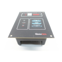
Explains the three-digit LCD display showing winding temperatures and maximum stored temperature with icons.
Describes the five LEDs (Yellow FAN, Red ALARM, Red TRIP, Red RELAY 4, Red RELAY 5) indicating operational status.
Details the internal buzzer that sounds on ALARM activation and can be silenced by the button.
Explains the operation of MANUAL/AUTO FAN, SILENCE/TEST, and MAX TEMP RESET buttons for control and testing.
Describes the built-in function that cycles fans ON for short periods at intervals for maintenance.
Lists key performance metrics including input power, consumption, measurement range, accuracy, and contact ratings.
Details physical dimensions, mounting options (panel, hinge, wall), weight, and terminal types for different configurations.
Lists certifications like UL, Canadian Standard C22.2, and CE declaration.
Guides users through installing the ITM Configuration software and necessary USB drivers on Windows XP/7.
Explains how to manage configuration files using the software, including creating new or opening existing files.
Details the parameters configurable via the software, such as active channels, set points, relay states, and fan exerciser settings.
Outlines setting up Modbus data link parameters like baud rate, parity, and stop bits using the software or front panel.
Provides step-by-step instructions for changing set points directly on the unit without a computer.
Discusses environmental factors and mounting practices to ensure accurate thermocouple readings.
Describes a laboratory procedure for testing ITM accuracy using simulated thermocouple readings and an ice bath reference.
Lists common error codes (Failed Sensor, A/D Converter, EEPROM, Display Driver) and their impact on unit operation.
Explains error conditions related to unstable sensor connections and reversed thermocouple wiring, including diagnostic displays.
Covers installation category, mains supply, grounding, and circuit breaker requirements for European installations.
Identifies the types of fuses used, their locations, and procedures for replacement by trained personnel.
Step-by-step guide for installing the ITM Configuration software and associated drivers on Windows 7.
Details the wiring for the RS-485 port and explains the Modbus RTU protocol used for communication.
Lists Modbus registers for reading temperature, status, and stored data, along with their corresponding data formats and comments.
| Type | Transformer Monitor |
|---|---|
| Power Supply | 24 VDC, 100-240 VAC |
| Output | 4-20 mA, Relay, Digital |
| Storage Temperature | -40°C to +85°C |
| Communication Protocols | Modbus |
| Operating Temperature | -40°C to +85°C (-40°F to +185°F) |