SYSTEM OVERVIEW ABOUT THE SYSTEM
1-9
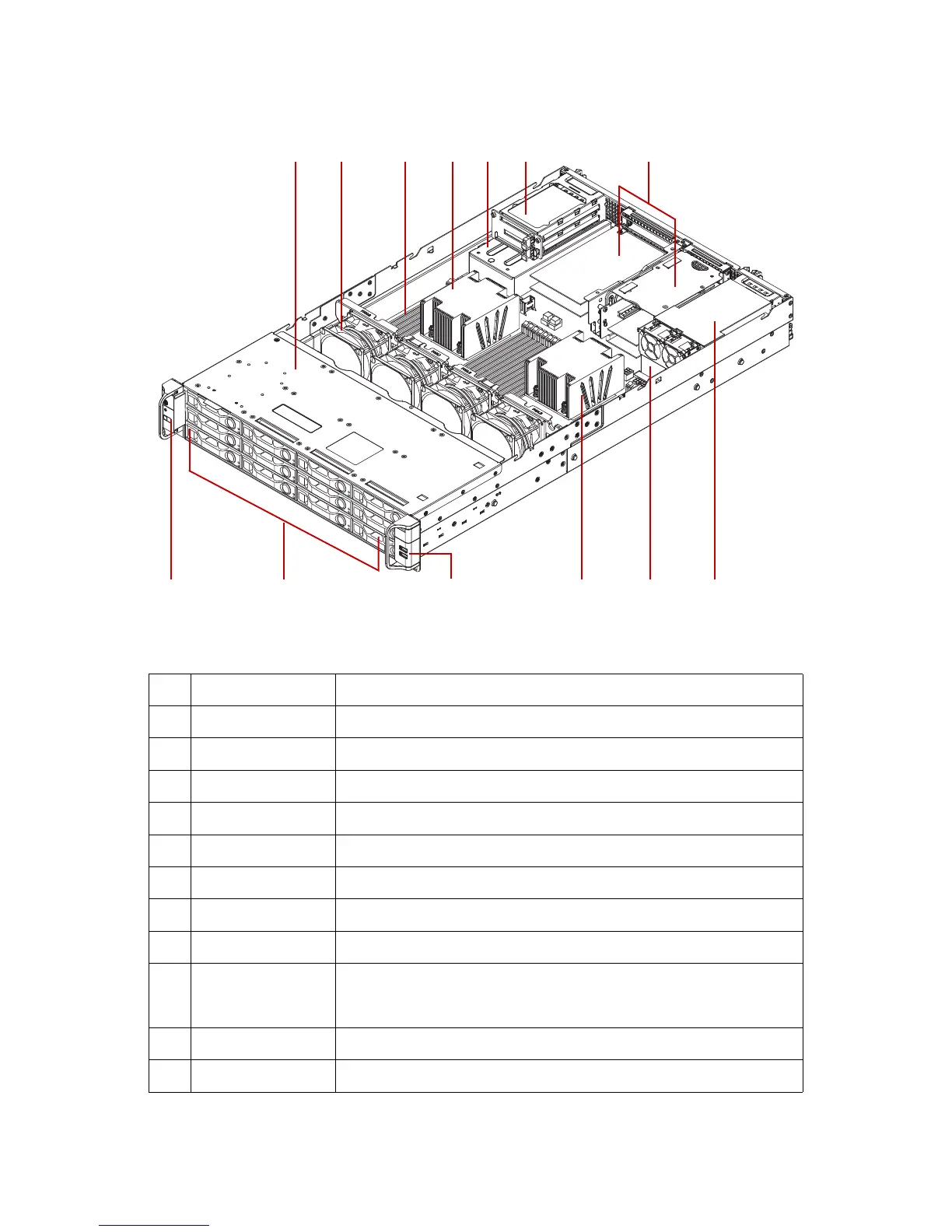
The 3.5” HDD configuration system overview is displayed in the following image:
Figure 1-2. 3.5” System component overview*
* CONFIGURATION MAY VARY BY MODELS.
Table 2: Component Overview
NO.ITEM DESCRIPTION
1 Top front cover Enclosure for hard disk drives bay.
2 Fan modules System fan modules (x4).
3 DIMM slots DDR4 DIMM slots, 12 per CPU.
4 Processor CPU01 and CPU02 processors with heat sinks* on top.
5 PSU assembly Redundant power supply unit assembly.
6 Expansion slots SSD optional expansion bay. (*only for QuantaGrid D51B-2U)
7 Expansion slots PCIe expansion bay*.
8USB board USB ports.
9 HDD assembly
3.5” model: 12 x hard disk drive assemblies
2.5” model: 24 x hard disk drive assemblies
(*only for QuantaGrid D51B-2U)
10 Front control panel On/Off power button and LED.
11 Middle top cover Only for QuantaGrid D51B-2U, 2.5” model