Do you have a question about the QUANTA QSSC-S99K 2U and is the answer not in the manual?
Device compliance with FCC rules for harmful interference in commercial environments.
Digital apparatus compliance with Canadian Interference-Causing Equipment Regulations.
Product compliance with European Low Voltage and EMC Directives.
Table indicating hazardous substance content in components against SJ/T 11363-2006.
Guidelines for server placement concerning service personnel access and user visual field.
Safety precautions for securing and loading servers in a rack.
List of items to verify after unpacking the QSSC-S99K 2U server system.
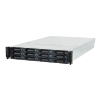
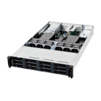
Description of the external features of the hot-swap version of the QSSC-S99K 2U.
Details on front and rear panel controls and LED indicators for system status.
Guidelines to prevent damage from static electricity and ensure safe working practices.
Illustration and identification of key components on the mainboard.
Step-by-step instructions for installing Hard Disk Drives (HDDs) into the system.
Procedure for removing the server's top chassis cover.
Detailed instructions for safely installing Central Processing Units (CPUs).
Procedure for installing DDR3 DIMM memory modules into the slots.
Comprehensive steps for removing and replacing the system's motherboard.
Overview of BIOS support for system features and standards.
List of key features and capabilities provided by the BIOS.
Explanation of the Power-On Self Test process and error handling by BIOS.
List of BIOS hotkeys for accessing setup and performing actions during POST.
Details on SMBIOS version support and system information.
Explanation of ACPI states (S0, S1, S4) supported by the system.
Information on using INT 15H, E820H call for querying system memory address map.
Overview of AST2050 BMC functionality and communication interface.
Glossary of terms and acronyms used in the BMC section.
Concept block diagram and role of BMC in server management.
Summary of essential features and capabilities of the BMC.
Description of POST progress codes, error messages, and system responses.
List of supported IPMI 1.5 and 2.0 commands.
Commands related to retrieving and managing sensor data records.
Details on AST2050 temperature sensors and threshold monitoring.
Explanation of watchdog timer functionality and timeout action support.
Defines sensor relate SDR format and provides sensor type SDR definition tables.
Overview of ESMS web utility for system information and remote management.
Details on web GUI requirements, login, and system management interface.
Procedure for logging into the BMC web interface using username and password.
Viewing system information, BMC details, firmware, and BIOS versions.
Displays Field Replaceable Unit (FRU) information for system components.
Information on CPU and memory slots, including ID, status, and model.
Controls and displays the status of the server's indicator LED.
View sensor readings and event logs for server health monitoring.
Displays all sensor readings and threshold settings from the managed system.
Displays system events logged by BMC, BIOS, or OS, with sorting capabilities.
Access to various configuration settings: Alerts, Network, SOL, Users, PEF, SSL.
Configure alert destinations for platform events via email or SNMP trap.
Configuration options for absolute or relative mouse cursor control.
Configure Platform Event Filters to define actions for system events.
Settings for network configuration, including IP address and VLAN.
Procedure for uploading new SSL certificates and private keys.
Configuration options for enabling and managing VLAN functionality.
Configuration settings for Serial Over LAN, including baud rate and privilege level.
Allows adjustment of the web session timeout value.
Configuration of the community string for SNMP trap server.
Configuration of the IP address for the SMTP mail server.
Managing user accounts: adding, modifying, and deleting users.
Setup instructions for Internet Explorer to enable KVM console redirection.
Configuration steps for Internet Explorer to support KVM console redirection.
Access to help information, including About JViewer for version details.
Initiate Console Redirection and view Server Power Status.
Launch the redirection console via Java viewer for remote server management.
View current power status and remotely control server power operations.
Select the preferred language from the available languages list.
Definition table for web user privileges and access rights.
Controls for video redirection, including start, stop, and full-screen modes.
Mapping of client keyboard keys to host keyboard functions during redirection.
Options for mouse synchronization and cursor control during remote sessions.
Controls for device redirection, including CD-ROM, ISO, Floppy, and Floppy Image.
Essential precautions and tools required before starting server maintenance.
Procedure for installing rack mount brackets onto the server chassis.
A systematic approach to diagnosing and resolving common server issues.
Diagnosing problems preventing the system from booting after installation or changes.
Detailed explanation of front and rear panel status LED indicators.
Description of status LEDs located on the front panel of the server.
Description of status LEDs located on the rear panel of the server.
Information on AMI POST checkpoints and beep codes for system debugging.
List of checkpoints during the bootblock initialization phase of the BIOS.
List of checkpoints occurring during the POST phase of the BIOS.
Table describing beep codes used in the boot block for error indication.
Details on POST error messages, their types (Warning, Pause, Halt), and handling.
| Form Factor | 2U |
|---|---|
| Memory | 24x DDR4 DIMM slots |
| Storage | Up to 24 x 2.5" |
| Power Supply | Redundant power supplies |
| Management | IPMI 2.0 with KVM over IP |
| Processor | Up to two Intel® Xeon® Scalable Processors |