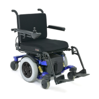
18 www.quantumrehab.com Quantum 6000
III. YOUR POWER CHAIR
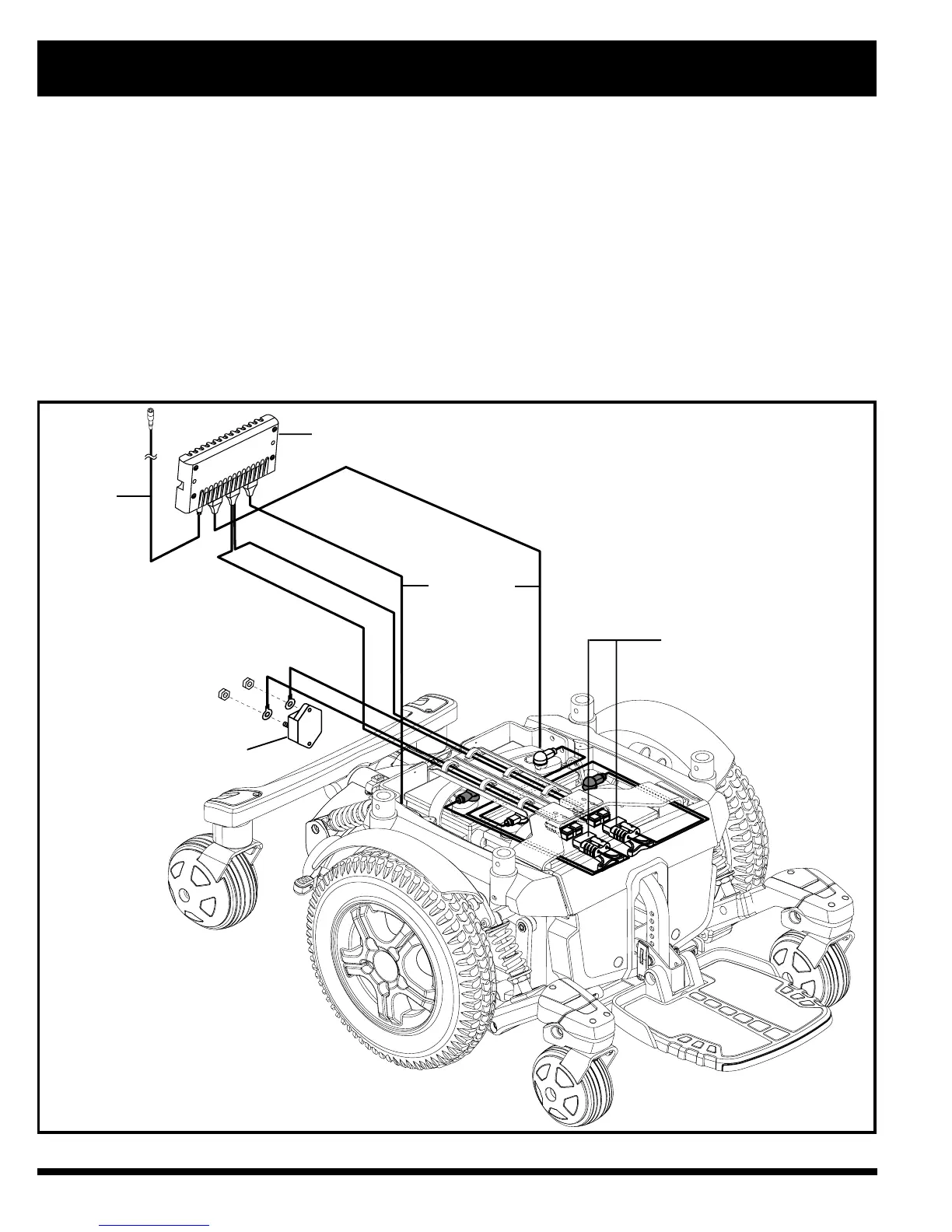
Motor Connectors: This is where the controller connects to the motors.
Battery Connector: This is where the controller connects to the batteries.
Controller Power Module: This enables the controller to communicate with the batteries and the motors.
Main Circuit Breaker (located on the rear main frame): The main circuit breaker is a safety feature built into your
power chair. When the batteries and the motors are heavily strained (e.g., from excessive loads), the main circuit breaker
trips to prevent damage to the motors and the electronics. If the circuit trips, allow your power chair to “rest” for approxi-
mately one minute. The circuit breaker will reset itself. Turn on the controller, and continue normal operation. If the main
circuit breaker continues to trip repeatedly, contact your Quantum Rehab Specialist.
Figure 7. Quantum 6000 Electrical Components
QUICK RELEASE
BATTERY CONNECTORS
MAIN CIRCUIT BREAKER
CONTROLLER
POWER MODULE
CONTROLLER
CABLE
TO MOTOR
CONNECTORS