40 www.quantumrehab.com Quantum 6000
Profile and Speed Indicator
The profile and speed indicator is a 5-segment illumi-
nated display that indicates speed setting as well as drive
profile.
Actuator Indicator
The actuator indicator is a 4-segment illuminated dis-
play that indicates power recline, power tilt, power leg
rest, and power elevating seat actuator modes.
Joystick Interface Module
The joystick interface module provides a means to enable
or disable the horn button, mode switch, on/off switch,
and speed adjustment dial.
NOTE: When a toggle switch is set to “J/S,” the
joystick has control of a particular function. When
the toggle switch is set to “Local,” control of this
function is disabled at the joystick.
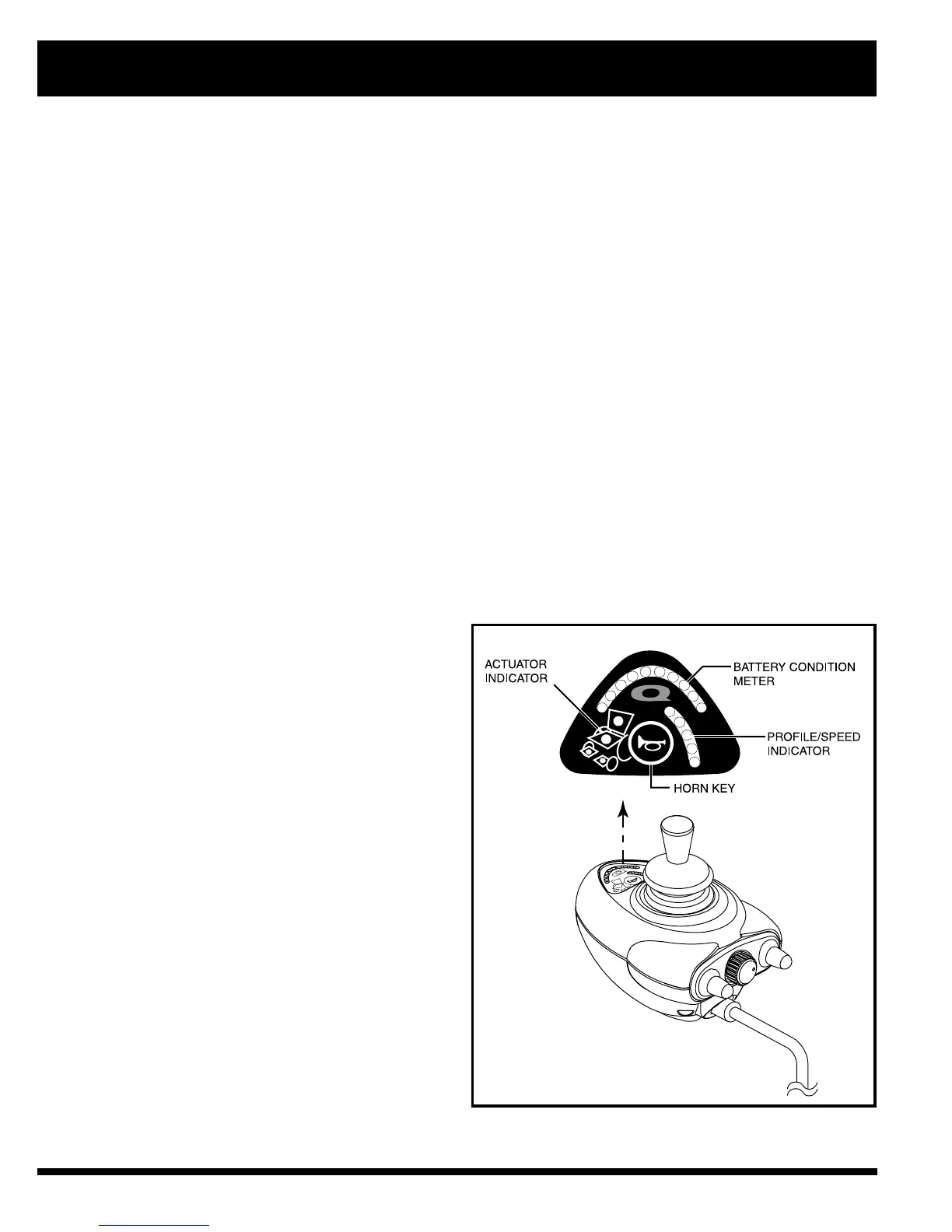
Display Pad
The display pad is located directly in front of the joystick. It contains the horn key, battery condition meter, profile /speed
indicator, and the actuator indicator. See figure 31.
Horn Key
The horn key activates the horn.
Battery Condition Meter
The battery condition meter is a 10-segment illuminated display that indicates that the Microdrive is powered on and also
gives the status of the batteries, the controller, and the power chair electrical system.
! Red, yellow, and green lights lit: Batteries charged; controller and electrical system OK.
! Red and yellow lights lit: Charge batteries if possible; controller and electrical system OK.
! Red lights only lit or slow flash: Charge batteries as soon as possible; controller and electrical system OK.
! Rapid flash of lights: Indicates a fault in the controller or the electrical system. See “Error Codes.”
! Ripple side to side of lights: The joystick was not in the neutral position when the controller was turned on. If you
get “ripple side to side of lights,” turn off the controller, allow the joystick to return to the neutral position, then turn on
the controller.
NOTE: If you still get “ripple side to side of lights,” contact your Quantum Rehab Specialist.
NOTE: When the batteries approach a discharged state, the first red light will begin to slowly flash, reminding you the
batteries need to be charged immediately!
Figure 31. Microdrive Display Pad
VII. OPERATION