Chapter 2: Basic Operations
DXi4700 Expansion Module
Quantum DXi4700 User’s Guide 51
Item Indicator, Button, or
Connector
Icon Description
1,2,3,4 SAS port (Input or Output) Provides connection from the Node or another
Expansion module.
5 Debut port Not used.
6 7-Segment Display Display the enclosure location in SAS Chain.
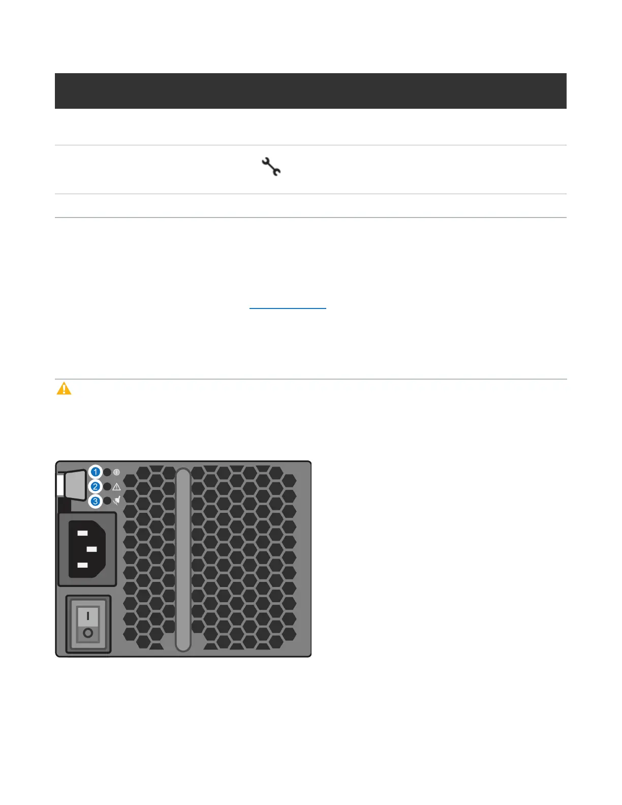
DXi4700 Expansion Module Power Supply Indicators
Each DXi4700 Expansion module power supply has LED indicators to show whether power is present or
whether a power fault has occurred (see Figure 28 below):
l DC Power - Lights green when the DC output voltage is within the limit.
l Power supply/cooling fan fault - Lights amber when a fault with the power supply or fan is detected.
l AC Power - Lights green when the AC output voltage is within the limit.
Caution: All power supplies are hot swappable. When replacing power supplies, never remove more
than one power supply at a time from the system. Also, before you remove one power supply, make
sure the other power supply is operating correctly (power indicator is green).
Figure 28: DXi4700 Expansion Module - Power Supply LED Indicators
1 - DC Power 2 - Power Supply Fault 3 - AC Power