EasyManuals Logo

QUBINO Smart meter User Manual

QUBINO Smart meter
51 pages
To Next Page IconTo Next Page
To Previous Page IconTo Previous Page
Page #29 background imageLoading...
Page #29 background image
EN.
29
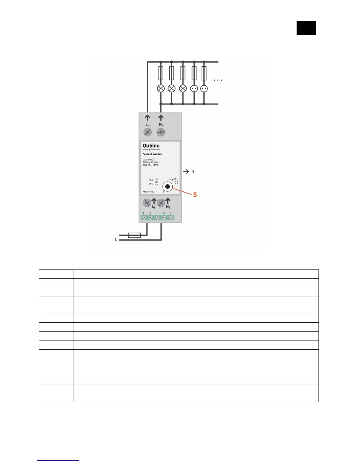
9. Electrical Diagram 230VAC
Notes for diagram:
LI
Live input
NI
Neutral input
Lo
Live output
No
Neutral output
1
Input for IR external relay/Ext. relay
2
Neutral lead for input
4
Live lead for External relay output
5
Output for External relay (max. 3W)
S
Service button (used to add or remove device from the Z-Wave network)
LED1
Device status. For detailed information please check the chapter “LED
SIGNALIZATION FOR INCLUSION/EXCLUSION”
LED2
External relay status. For detailed information please check chapter LED
SIGNALIZATION FOR INCLUSION/EXCLUSION
IR
Output for IR external relay
1imp/Wh
Red - Pulse rate (On no load indication)

Other manuals for QUBINO Smart meter

Questions and Answers:

Question and Answer IconNeed help?

Do you have a question about the QUBINO Smart meter and is the answer not in the manual?

QUBINO Smart meter Specifications

General IconGeneral
Communication ProtocolZ-Wave
Weight150 g
Rated Current65 A
AccuracyClass 1
Frequency50/60 Hz
Radio ProtocolZ-Wave
Power Consumption< 1 W
Z-Wave Frequency868.42 MHz (EU)
RangeUp to 30 m indoors
Operating Temperature-10°C to +40°C