EasyManuals Logo

Queclink GV310LAU User Manual

Queclink GV310LAU
20 pages
To Next Page IconTo Next Page
To Previous Page IconTo Previous Page
Page #9 background imageLoading...
Page #9 background image
GV310LAU User Manual
TRACGV310LAUUM001
9
3. Interface Definition
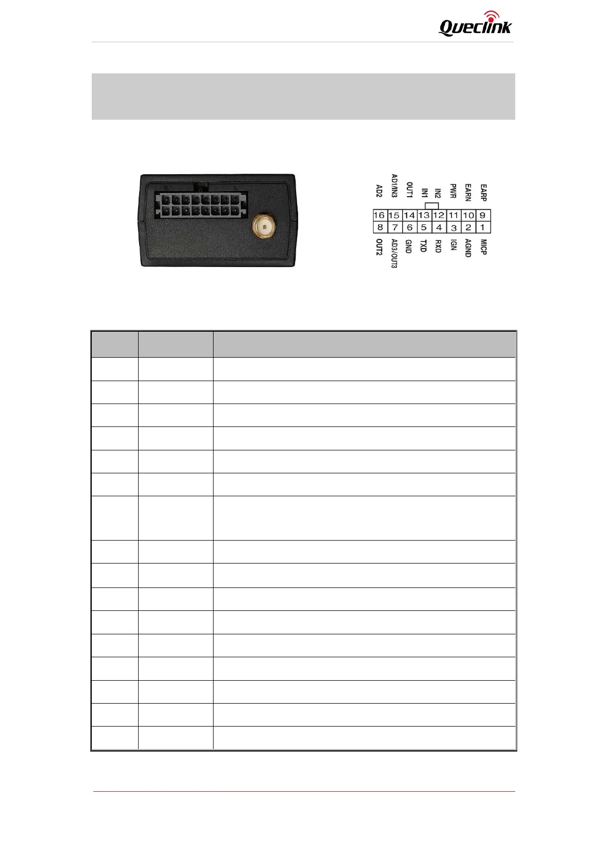
The GV310LAU has a 16-pin interface connector which contains the connections for power, I/O,
RS232, MIC, etc. The sequence and definition of the 16-pin connector are shown in the following
figure:
Figure 3. The 16-pin Connector on the GV310LAU
Table 6. Description of 16-pin Connections
Pin No.
Pin Name
Function Description
1
MICP
MIC positive input
2
AGND
MIC negative input
3
IGN
Ignition detection input, positive trigger
4
RXD
The RXD_RS232
5
TXD
The TXD_RS232
6
GND
Power and digital ground
7
AD3/OUT3
One special I/O can be configured as a 0-16V analog input or an
open drain output with 150 mA max drive current
8
OUT2
Open drain output2, 150mA max drive current
9
EARP
Speaker positive output
10
EARN
Speaker negative output
11
PWR
External DC power input, 8-32V
12
IN2
Digital input2, negative trigger
13
IN1
Digital input1, negative trigger
14
OUT1
Open drain output1, 150mA max drive current, with latch circuit
15
AD1/IN3
Analog input1 (0-16V) or digital input 3, negative trigger
16
AD2
Analog input2 (0-16V)

Questions and Answers:

Question and Answer IconNeed help?

Do you have a question about the Queclink GV310LAU and is the answer not in the manual?

Queclink GV310LAU Specifications

General IconGeneral
BrandQueclink
ModelGV310LAU
CategoryGPS
LanguageEnglish

Related product manuals