LTE Standard Module Series
EM05-G Hardware Design
EM05-G_Hardware_Design 29 / 69
The following table shows the definition of FULL_CARD_POWER_OFF#.
Table 8: Definition of FULL_CARD_POWER_OFF#
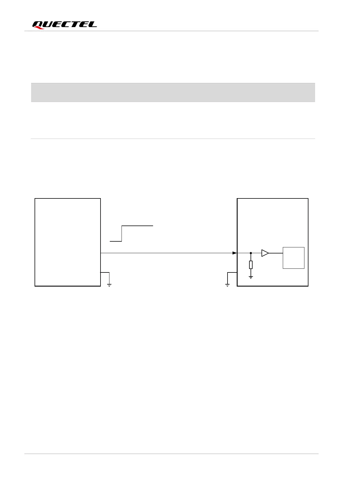
EM05-G can be turned on by driving the FULL_CARD_POWER_OFF# pin to a high level.
It is recommended to use a host GPIO to control FULL_CARD_POWER_OFF#. A simple reference circuit
is illustrated in the following figure.
Figure 9: Turn on the Module with a Host GPIO
The module can also be turned on automatically. The FULL_CARD_POWER_OFF# should be pulled up
to 1.8 V or 3.3 V (recommended) through a resistor, whose resistance should be 5–10 kΩ. In this case,
when the power supply of VCC is cut off, the module will be shut down.