LTE Module Series
EM05 Hardware Design
EM05_Hardware_Design Confidential / Released 30 / 59
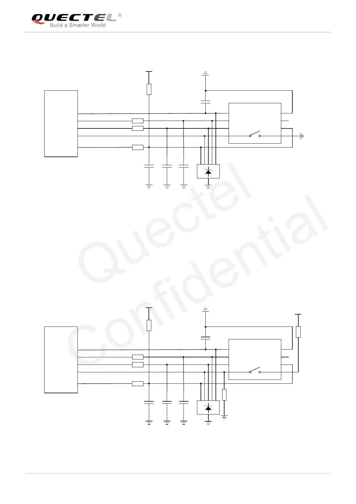
The following figure shows a reference design for normally short-circuited (U)SIM card connector.
Module
USIM_VDD
USIM_RST
USIM_CLK
USIM_DATA
USIM_DET
0R
0R
0R
100nF
(U)SIM Card Connector
GND
GND
33pF
33pF 33pF
VCC
RST
CLK
IO
VPP
GND
GND
USIM_VDD
15K
GND
CD SW
Figure 16: Reference Circuit of Normally Short-Circuited (U)SIM Card Connector
Normally Short-Circuited (U)SIM Card Connector
When the (U)SIM is absent, CD is short-circuited to SW and USIM_DET is at low level.
When the (U)SIM is inserted, CD is open to SW and USIM_DET is at high level.
The following figure shows a reference design for normally open (U)SIM card connector.
Module
USIM_VDD
USIM_RST
USIM_CLK
USIM_DATA
USIM_DET
0R
0R
0R
100nF
(U)SIM Card Connector
GND
33pF
33pF 33pF
VCC
RST
CLK
IO
VPP
GND
GND
USIM_VDD
15K
GND
CD
1.8V
4.7K
33K
SW
Figure 17: Reference Circuit of Normally Open (U)SIM Card Connector