Do you have a question about the Quectel EM05 and is the answer not in the manual?
Records changes and versions of the document.
Safety precautions for using the EM05 module during operation, service, and repair.
Overview of the EM05 series, its capabilities, and variants.
Detailed technical features and specifications of the EM05 module.
Block diagram illustrating the internal components and connections of the EM05.
Visual representation of the EM05 module's pin layout on the M.2 connector.
Detailed explanation of each pin's function, I/O type, and voltage domain.
Overview of different operational states like Normal, Airplane, Sleep, and Power Down modes.
Techniques and methods for reducing the EM05 module's power consumption.
Detailed explanation of the sleep mode and its power-saving mechanisms.
How to use USB for wake-up from sleep mode.
Alternative method for USB wake-up using WOWWAN# signal.
Configuration and behavior of the module in airplane mode.
Requirements and considerations for powering the EM05 module.
Methods to mitigate voltage drop during Tx power for stable operation.
Example circuit design for providing a stable power source to the module.
Using AT commands to check the module's voltage status.
Procedures and timing for powering the module on and off.
Hardware method to turn on the module using a specific control pin.
Methods to safely shut down the EM05 module.
Hardware shutdown procedure using the FUL_CARD_POWER_OFF# pin.
Software shutdown procedure using AT+QPOWD command.
How to reset the module using the RESET# pin and its timing.
Details of the (U)SIM card interface, including pin definitions and voltage support.
Specifications and reference circuit for the USB 2.0 slave interface.
Details on PCM digital audio interface and I2C serial interface for external codecs.
Description of control and indicator signals like W_DISABLE1#, LED#, WOWWAN#, etc.
Function of the W_DISABLE1# signal for enabling/disabling RF function.
How the LED# signal indicates RF status.
Behavior of the WOWWAN# signal for waking up the host.
Function of the DPR signal for dynamic power reduction/SAR detection.
Configuration pins for setting the M.2 interface type.
Overview of the integrated GNSS solution and supported systems.
Description of main and diversity antenna interfaces and operating frequencies.
Frequency specifications for the GNSS antenna.
Requirements for installing antennas, including main, Rx-diversity, and GNSS.
Specific technical requirements for GNSS and WCDMA/CDMA/LTE antennas.
Recommendation for RF connectors and their dimensions.
Electrical limits for power supply and voltage on pins.
Specifies the required input voltage range and typical values for the module.
Defines voltage levels for input and output signals.
Specifies the normal and extended operating temperature ranges for the module.
Detailed breakdown of current consumption under various operating modes and conditions.
Specifies the conducted RF output power for different frequency bands.
Details conducted RF receiving sensitivity for various frequency bands and modes.
Electrostatic Discharge (ESD) protection levels for different parts of the module.
Recommendations for thermal management and heat dissipation.
Drawings and dimensions of the EM05 module itself.
Standard dimensions and pinout for the M.2 connector used by the module.
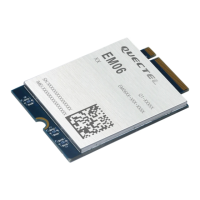
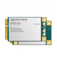
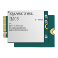
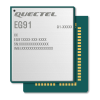
Visual representations (top and bottom views) of the module's physical layout.
Compliance and standards related to the M.2 connector used.
Information on how the EM05 module is packaged and quantities.
| Brand | Quectel |
|---|---|
| Model | EM05 |
| Category | Control Unit |
| Language | English |
