2016/5/17
B
Reference DesignL76 Series
Tony GAO
Storm BAO
CHECKED BY
DRAWN BY
OF
A
6
5
4
32
1
SHEET
A
B
C
D
123456
D
C
B
Quectel Wireless Solutions
PROJECT
SIZE
TITLE
VER
41 DATE
A2
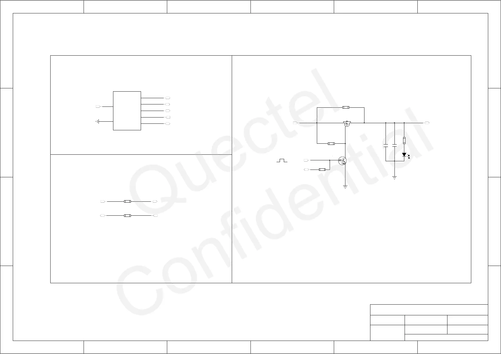
UART Circuit
Power Management Circuit (Optional)
3.3V Power Suppply and UART Circuit
Customer's MCU
Generally, 100R for R102 and R103 is recommended, but 0R also works well.
R102, R103 are reserved for debugging the waveform of UART,
and they are also beneficial to ESD protection.
There are two ways to enter into backup mode and back to full on mode, you can choose
1. Send command “$PMTK225,4*2F” to enter into backup mode forever. The only way to
wake up the module is pulling the FORCE_ON high. Here, Q101, Q102, R101 are not
2. Cutting off VCC and keeping V_BCKP powered will make the module enter into backup
mode from full on mode. As long as the VCC pin is powered, the module will enter into full on
the dedicated way base on your requirement.
mounted; R104 and R106 are 0 ohm.
mode immediately. Here, Q101, Q102, R101 are mounted; R104 and R106 are not mounted.
C102
100nF
R105
1K
D101
C101
4.7uF
Q101
SI2333DS
R101
10K
Q102
DTC143ZEBTL
R104
NM_0R
VCC
GND
GPIO_X
RXD
GPIO_X
TXD
GPIO_X
U101
MCU
R102
100R
R103
100R
R106
NM_OR
VCC_MCU_3.3V
GPS_EN
TXD_MCU
RXD_MCU
GPIO_RESET
GPIO_STANDBY
TXD_MCU
RXD1_MODULE
RXD_MCU
TXD1_MODULE
GPS_EN
VCC_MODULE_3.3V
VCC_MCU_3.3V
FORCE_ON

 Loading...