2016/5/17
Storm BAO
Tony GAO
CHECKED BY
DRAWN BY
OF
A
6
5
4
32
1
SHEET
A
B
C
D
123456
D
C
B
Quectel Wireless Solutions
PROJECT
SIZE
TITLE
VER
44
B
DATE
Reference DesignL76 Series
A2
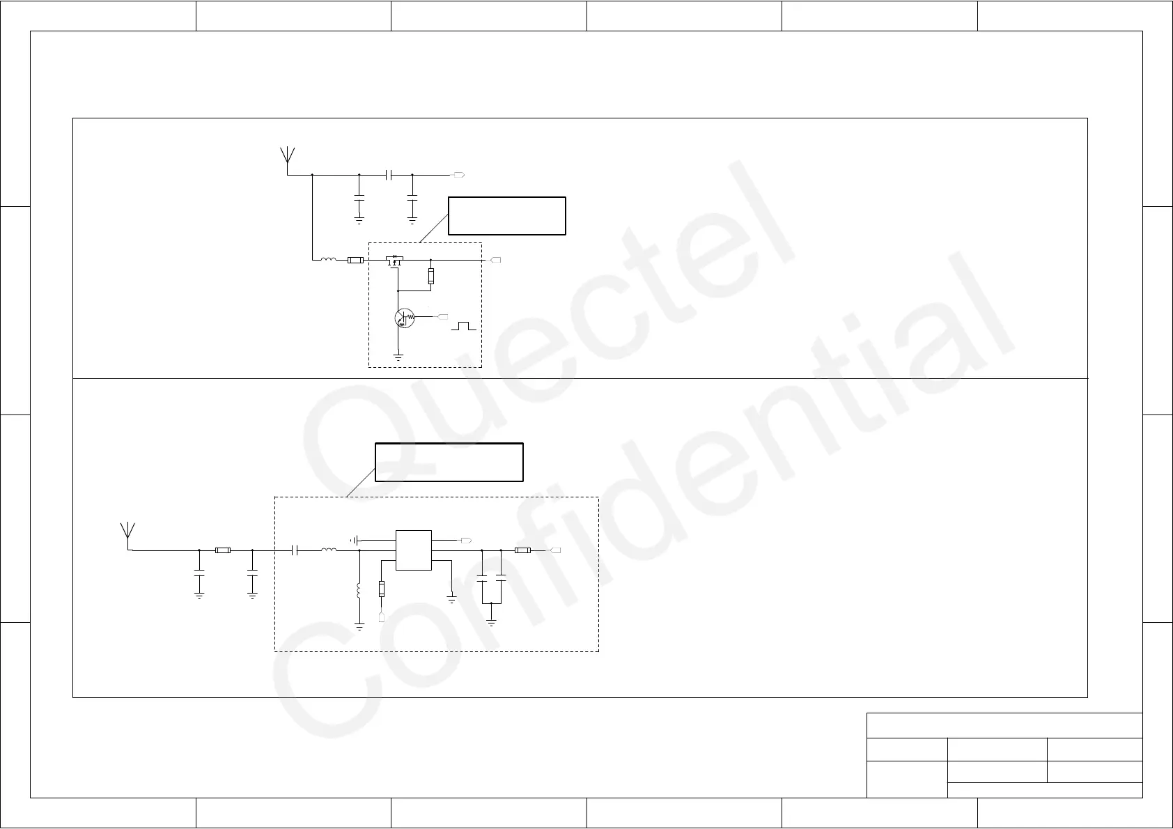
Antenna Interface
1. Pi circuit (C401, C402, C403) is reserved for impedance matching for antenna.
For more details, please refer to L76 Series Hardware Design.
5. Impedance of RF trace should be controlled as 50 ohm and the trace length
should be kept as short as possible.
2. VCC_RF can be used as power supply for active antenna. Its typical value is 3.3V,
and the voltage ranges from 2.8V to 4.3V (VCC_RF=VCC). If it does not meet the
By default, C402 and C403 are not mounted; C401 is 100pF.
1.There is no need to use an external LNA for L76-L module
because an embedded LNA is already used inside the module.
Active Antenna
Passive Antenna
requirement of the active antenna, an external LDO could be used.
3. The voltage level of ANTON will be pulled down in standby mode.
4. If the L76 series module never enter into standby mode in the design, the ANTON
pin should be kept floated.
Optional:used to save
power if necessary.
(Optional)
LNA Circuit
2. Pi circuit (R405, C405, C406) is reserved for impedance matching for antenna.
By default, C405 and C406 are not mounted; R405 is 0R.
3. If an external LNA is added between passive antenna and L76/76B module, the total
sensitivity will be improved by about 3dB, which is beneficial for improving TTFF.
4. One typical reference circuit with BGA524N6 is given in the left figure. Here,
By default, C407 is 1nF; L402 is 8.2nH; and L403 is not mounted.
For more details, please refer to L76 Series Hardware Design.
7. Impedance of RF trace should be controlled as 50 ohm and the trace length should be
kept as short as possible.
5. VCC_RF can be used as power supply for LNA. Its voltage range is from 2.8V to 4.3V,
and its typical value is 3.3V (VCC_RF=VCC)
6. ANTON is an optional pin which can be used to control the enable pin of an external
LNA. If “ANTON” function is not used, please connect the pin “LNA ENABLE”
to VCC to keep LNA always on.
C407, L402 and L403 form a reserved matching circuit for the LNA BGA524N6.
No need to add for L76-L
which has an embedded LNA
C401
100pF
J401
Active Antenna
C403
NM
C402
NM
R401
10R
L401
47nH
R402
10K
Q401
SI2333
Q402
DTC143ZEBTL
R405
0R
J402
Passive Antenna
C406
NM
C405
NM
C409
33nF
C408
100pF
L402
8.2nH
L403
NM
4
GND
5
AI
6
PON
3
AO
2
VCC
1
GND
U401
BGA524N6
C407
1nF
R403
100R
R404
100R
VCC_RF
RF_IN
ANTON
VCC_RF
RF_IN
ANTON

 Loading...