UMTS/HSPA/LTE Module Series
UMTS<E EVB User Guide
UMTS<E_EVB_User_Guide Confidential / Released 19 / 32
Table 6: Pin Assignment of J602
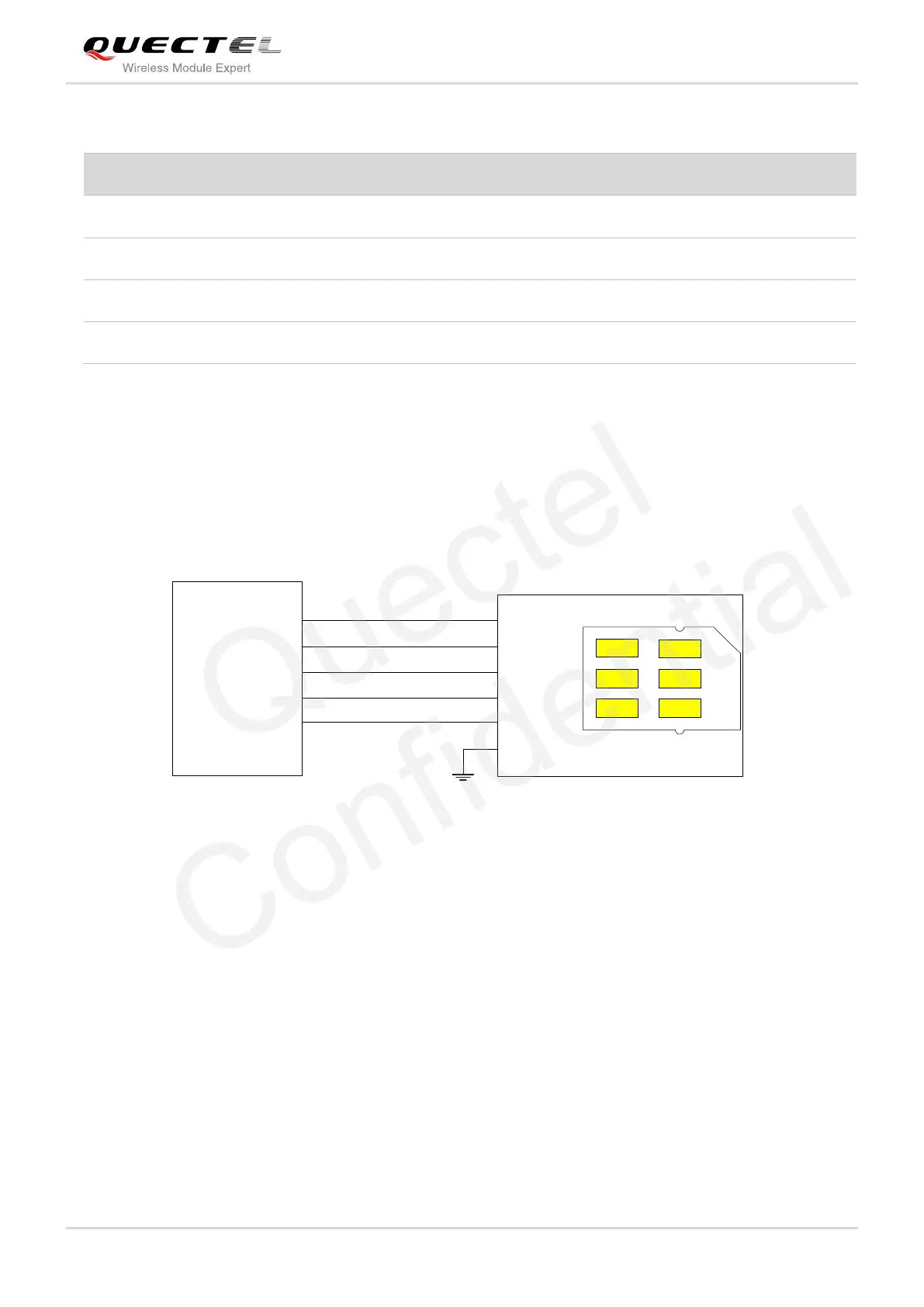
3.4. USIM Card Interface
The UMTS<E EVB has a USIM card interface. A suitable USIM card (3V or 1.8V) is required to start the
UMTS<E module. Figure 14 shows the simplified interface schematic for J702.
USIM card holder
USIM_VDD
USIM_CLK
USIM_DATA
USIM_RST
USIM_GND
J101
J702
C1
C7
C2
C3
Push-Push
USIM_VDD
USIM_DATA
USIM_RST
USIM_CLK
12
10
8
6
USIM_PRE.
GN
D
USIM_PRESENCE
14 CD2
CD1
Figure 14: Simplified USIM Card Interface Schematic
Negative microphone input
Negative loud speaker output
Positive loud speaker output
Positive microphone input

 Loading...


