UMTS/HSPA/LTE Module Series
UMTS<E EVB User Guide
UMTS<E_EVB_User_Guide Confidential / Released 13 / 32
3 Interface Application
This chapter describes the hardware interfaces of UMTS<E EVB, shown as follows:
Power interface
USB interface
Audio interface
USIM card interface
UART interface
It also provides information about LEDs, buttons and test points to help you use the UMTS<E EVB.
3.1. Power Interface
The power supply of UMTS<E EVB could come from the external input which is connected with power
jack or USB receptacle. The power jack and USB receptacle connects a step-down converter which can
provide the supply voltage (VBAT) required for operating EVB and UMTS<E module.
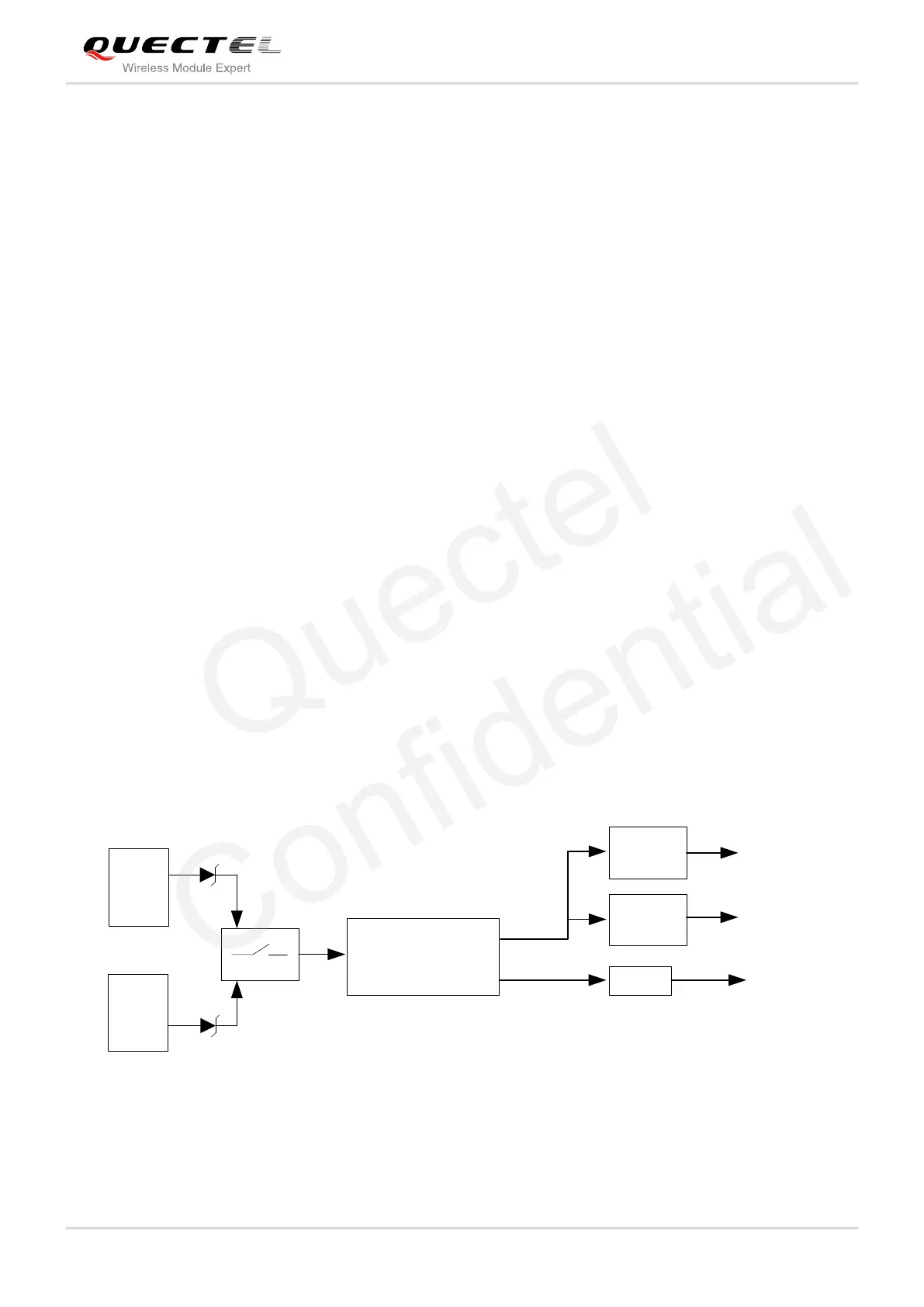
Figure 4 shows the simplified power supply schematic, and Figure 5 shows the power interface of
UMTS<E EVB.
J201
S201
Power
supply
Power
switch
Step-down converter
U201
AAT2138
J102
VBAT
Power supply to
UMTS<E module
1.8V
3.0V
U302
LDO
U303
LDO
J801
USB
interface
Figure 4: Simplified Power Supply Schematic

 Loading...


