Do you have a question about the Quick 969D+ and is the answer not in the manual?
Identifies the main parts of the soldering station using a diagram and table.
Details the function of each button on the soldering station interface.
Describes the icons and text displayed on the LCD screen.
Provides step-by-step instructions for connecting the soldering station.
Shows the physical dimensions of the soldering station with a diagram.
Explains how to increase and decrease the soldering temperature.
Details the process for setting specific temperature points on the station.
Guides on how to input the current password to proceed.
Outlines the procedure for safely removing the heater from the soldering station.
Details the steps involved in installing a new heater into the station.
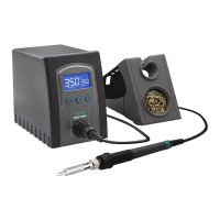
The QUICK 969D+ is a lead-free soldering station designed for ease of use and efficient operation. Its simple and compact shape makes it convenient for various soldering tasks. This instruction manual provides comprehensive guidance on its installation, operation, maintenance, and troubleshooting.
The primary function of the QUICK 969D+ soldering station is to provide a controlled heat source for soldering applications, specifically designed for lead-free soldering. It achieves this by rapidly heating and recovering temperature, ensuring efficient and reliable solder joints. The station features an LCD display for clear temperature indication and allows for flexible and convenient temperature adjustment and calibration through its button interface.
Temperature Control and Adjustment: The soldering station offers precise temperature control. In the main menu, you can increase or decrease the temperature by 1°C with a single press of the respective buttons. Holding the buttons down allows for continuous temperature adjustment. The station also features three pre-set temperature points that can be customized. To set a temperature point, navigate to the temperature point window, press the "" button to cycle through the three points, adjust the temperature using the up/down buttons, and then long-press the "" key to save the setting. The display will show "SAVE" to confirm.
Password Protection: For enhanced security and to prevent unauthorized temperature changes, the soldering station includes a password setting feature. When the password lock is active, temperature settings cannot be modified, but you can still freely select between the three pre-set temperature points. To enter the password setting mode, turn off the power, then simultaneously hold down the "up" and "down" buttons while turning the power back on. Continue holding until the display shows a specific pattern, indicating entry into the parameter input mode.
Password Setting Procedure: Once in the parameter input mode, press the "" button. The window will display "---", and the 100's digit will flash, allowing you to input the initial password. Use the "up" or "down" buttons to select the desired digit, then press "" to move to the next digit (tens, then ones). The input method is consistent across all digits. If the password is entered incorrectly the first time, the interface will reset, displaying "---" again for re-entry. If the password is wrong a second time, the display will show "Err", and the station will return to its normal working state without entering parameter settings. A correct password grants access to the parameter settings.
New Password Setting: Within the parameter menu, select "02" and press "" to enter the new password setting interface. The window will display "--", and the hundred digit will blink. Use the "up" or "down" buttons to select the hundreds digit, then press "" to move to the tens digit, and similarly for the ones digit. After selecting the ones digit, press "*" to enter the second password. The process for setting the second password is identical to the first. If the two passwords do not match, the station will return to the working state, and the password setting will not be successful. If the passwords match, the display will show "SAVE", confirming successful password setting, and then return to the parameter menu selection interface.
Installation and Connection: Connecting the soldering station is straightforward. First, connect the 5-pin plug into the station, ensuring the pin aligns with the groove in the connection socket. Place the soldering iron handle in its designated holder. Next, insert the power plug into a grounded power socket. Finally, turn on the power switch to begin operation.
LCD Display Descriptions: The LCD provides clear visual feedback on the station's status. The "heating state" icon indicates when the iron is actively heating. The "buzzer" icon shows whether the audible buzzer is turned on or off. "Real Temp" displays the current temperature of the soldering iron tip, while "Set Temp" shows the desired target temperature.
Tip Maintenance: Proper tip maintenance is crucial for extending the life and performance of your soldering iron.
Soldering Station Heater Replacement: The heater is a replaceable component. The process involves several steps to ensure safe and correct replacement.
Temperature Calibration: Temperature calibration is necessary whenever the handle, heating element, or soldering tip is replaced.
Fault Descriptions: The station provides error codes to help diagnose issues:
| Tip to Ground Resistance | <2Ω |
|---|---|
| Tip to Ground Potential | <2mV |
| Tip Type | Interchangeable |
| Voltage | 220V |
| Cable Length | 1.2m |
| Temperature Range | 200°C - 480°C |
| Temperature Stability | ±2°C (in still air, no load) |