BTQ Series
EN
QUICK BTQSeries INSTALLATION AND USER’S MANUAL - REV003A
11
4 - Installation
4.2 - Thruster
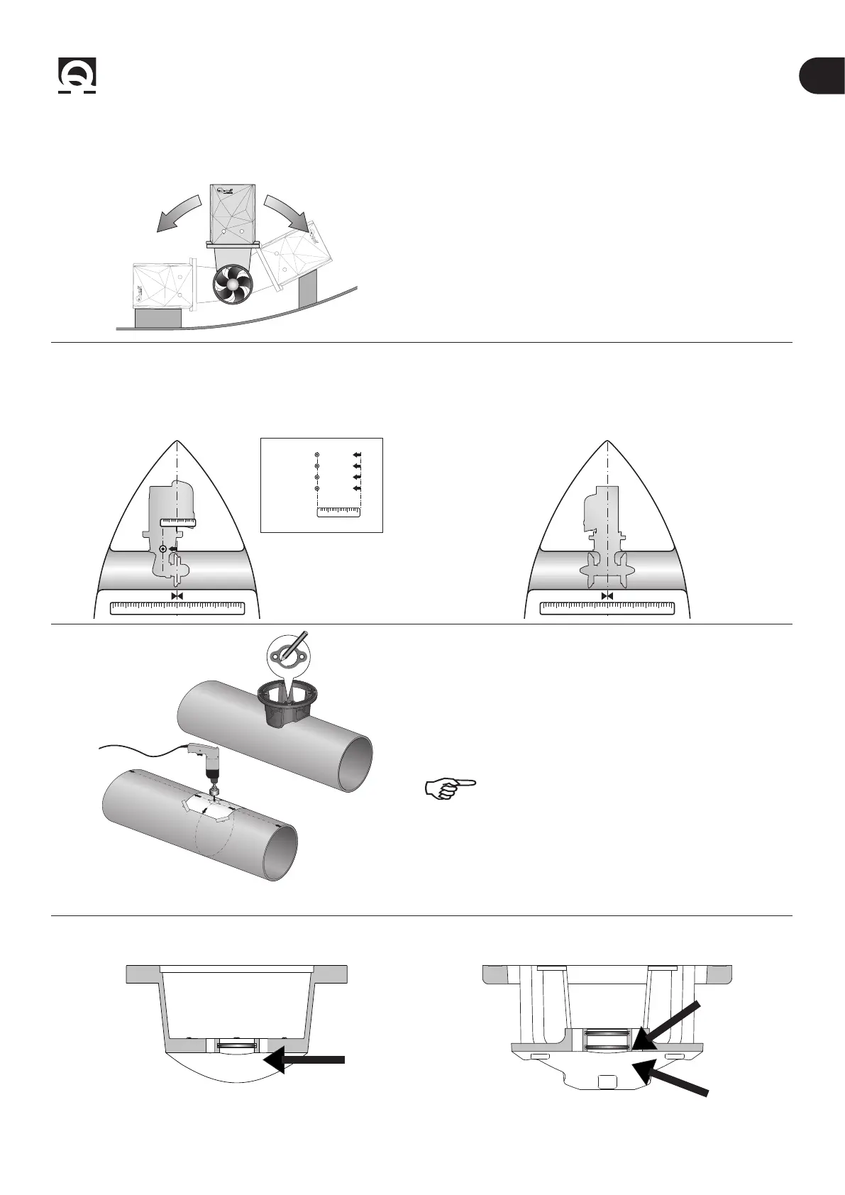
• The thruster can be installed at any angle within 90º from
the vertical.
• If the electric motor is positioned at an angle of more than
30° from the vertical, an appropriate support (saddle) must be
installed.
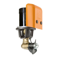
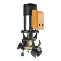
SINGLE PROPELLER DOUBLE PROPELLER
• To position the thruster in the tube, nd the half-way point
of the tube and move by the value indicated (left or right, see
box) in the diagram below so that the propeller is positioned
exactly in the middle of the inner length of the tunnel.
• To position the thruster in the tube, nd the half-way point
of the tube and move by the value indicated (left or right, see
box) in the diagram below so that the propeller is positioned
exactly in the middle of the inner length of the tunnel.
10 2 3 4 5 6 7 8 9 10
10 2 3 4
10 2 3 4
BTQ110 50 mm
BTQ125 50 mm
BTQ140 50 mm
BTQ180 50 mm
10 2 3 4 5 6 7 8 9 10
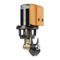
• Use the ange to mark the centre of the holes on the tube.
• Fix the drilling template on the reference points, making
sure they are aligned with precision at the half-way point of
the tube.
N.B. All holes must be exactly aligned with the half-
way point of the tunnel, since tolerance between
propeller and tunnel is minimal.
• Take care that there are no resin residues in the contact
area between ange and tube; this could cause misalignment.
Any resin residues and any other hindrance to correct
contact must be removed with sandpaper.
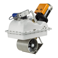
BTQ Ø110/125 BTQ Ø140/185/250/300
• Insert one O-ring into the special seat inside the ange. • Insert two O-rings into the special seats inside the ange.