BTQ Series
EN
QUICK BTQSeries INSTALLATION AND USER’S MANUAL - REV003A
13
4 - Installation
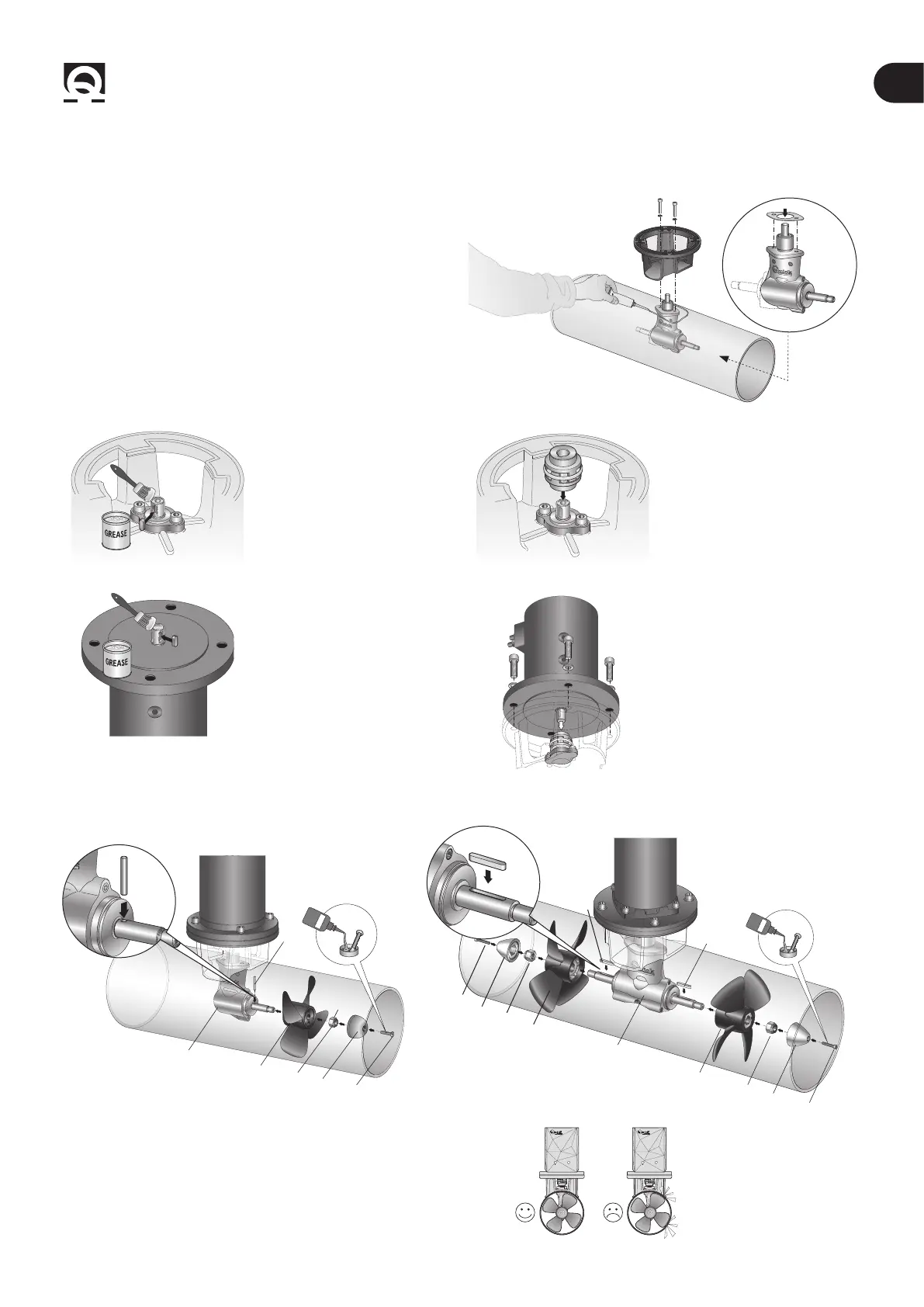
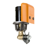
4.4 - BTQ 140/185/250/300 Gearleg and motor support flange
• Fit the gearleg with the special seal gasket.
SILICONE
• For further protection against the entry of water, apply
silicone for nautical use around the point of contact between
ange and tube.
• Fasten everything with the ange using the special screws
and washers.
1
• Grease the terminal part of
the gearleg shaft; t the small
key into its seat.
2
• Insert the elastic coupling
in the terminal part of the
gearleg shaft.
3
• Grease the terminal part of
the drive shaft; t the key into
its seat.
4
• Insert the motor onto the
elastic coupling; secure
it with the 4 screws and
washers supplied.
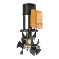
4.4.0 - BTQ140/185/250/300 Single propeller/double propeller assembly
LOCTITE
D
A
B
C
D
E
F
PIN
LOCTITE
A
B
C
D
F
E
C
D
E
F
A
KEY
Propeller(s) assembly
Insert the drive key/pin A on gearleg B; t the propeller C to the
gearleg by engaging it to the drive key/pin A; secure the propeller
with the self-locking nut D. Insert anode E on nut D and lock it with
screw F smeared with threadlocker (loctite type).
WARNING: on conclusion
of assembly, make sure
that the propeller is
exactly positioned at the
central point of the tunnel.