BTR Series
EN
QUICK BTR Series INSTALLATION AND USER’S MANUAL - REV 001C
13
4 - Installation
Fig. 12
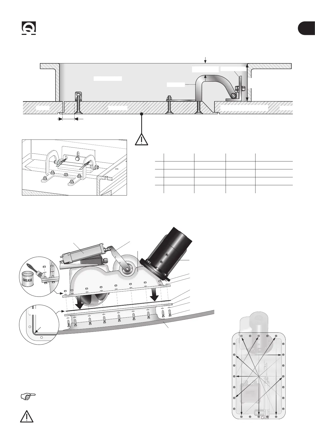
• Drill the angle bracket and also secure the other two M8 screws (g. 13) rmly.
Fig. 13
WARNING: for a sturdy xing of the hinge and bracket, the
hatch must not have hollow areas, or non-structural inlling (g.
12).
D
HATCH
B
COUNTER FLANGE
HINGE
ANGLE BRACKET
HULLHULL
A
Hull: C
Ø140 Ø185 Ø250 Ø300
A Min 5mm Min 5mm Min 5mm Min 5mm
B 37-57mm 60-65mm 65-80mm 110-120mm
C 30mm 35mm 40mm 40mm
D 5 mm 15mm 20mm 20mm
Fig. 15
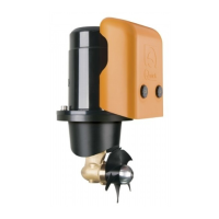
• Remove the previously applied adhesive protectors from the counter ange.
• Verify that the O-ring seat is well cleaned and has not been damaged during installation.
• Position the O-ring correctly on the counter ange (ref. 14A), assemble the retractable
thruster (g.14), spread marine grease on the bolt threads (ref. 14B) and x securely with
the supplied screws.
4.3 - Retractable thruster installation
1
2 3
10 9
4
8
7
12
11
6
5
The counter ange screws should be tightened to 15Nm, tightening little by little
in a cross pattern as in the example in gure 15.
WARNING: after about a week from installation, check the correct tightening of
the screws to compensate for any settling of the O-ring.
Fig. 14
O-RING
BOLT
WASHER
MOTOR
WASHER
NUT
COUNTER FLANGE
HULL
PROPELLER
ACTUATOR
ACTUATOR
LEVER
O-RING
Ref. 14A
Ref. 13B