BTR Series
EN
QUICK BTR Series INSTALLATION AND USER’S MANUAL - REV 001C
15
4 - Installation
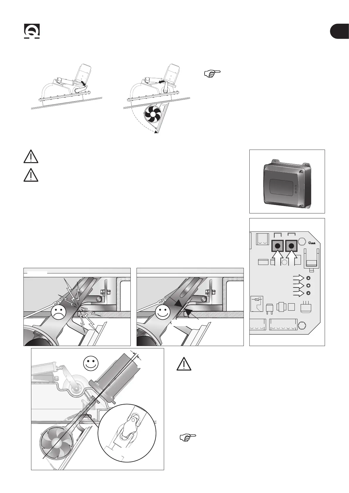
Make sure the system can be closed
and opened again smoothly without
mechanical hindrance.
4.7 - Adjustment procedure
WARNING: the following procedure must be performed by qualied personnel.
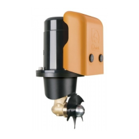
Fig. 18
RTC R1
WARNING: presence of moving mechanical parts. Take special care when
operating on a powered retractable thruster.
• Make sure that all electrical connections have been made correctly.
• Remove the cover from the RTC R1 board housing (g.18).
• Switch to “manual mode” to adjust the limit switches.
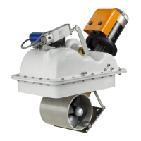
• Press and hold down both the UP and DOWN buttons on the board (g. 19) to power the
RTC R1 electronic board until the POWER LED (green) ashes rapidly (g. 19 ref. A). Then
release both buttons.
• Now it is possible to control the actuator electrically with the UP and DOWN buttons.
• Press the DOWN button until reaching a stroke that allows the actuator to be hooked to
the lever (point 4.5 - g. 16 ref. A).
• Pressing the DOWN button opens the thruster until the limit switch is activated and the
STATUS LED turns green (g. 19 ref. B).
• The limit switch can be adjusted (point 4.8) if not in the right position (g. 20A).
CAN2
UP DWN
CN3
POWER
LA STATUS
ERROR
COM COM C
-
COMC
-
SXC
-
DXI
-
SXI
-
DXLSO
Fig. 19
A
C
B
RTC R1 PCB
Fig. 20A
8/10 mm
Fig. 20B
± 5°
CONSTANT
VELOCITY JOINT
WARNING: check that the CV joint is in a straight
position, at an angle between -5° and +5° (Fig.20b)
• By pressing the UP button it is now possible to verify hatch
closing and once the limit switch is reached, the STATUS LED
turns red. If the stroke is not enough to reach the limit switch,
adjust the latter during closing (point 4.8).
The retractable thruster is factory-set, so it should
not be necessary to adjust it during closing.