BTR Series
EN
QUICK BTR Series INSTALLATION AND USER’S MANUAL - REV 001C
9
4 - Installation
4.1 - Counter flange installation
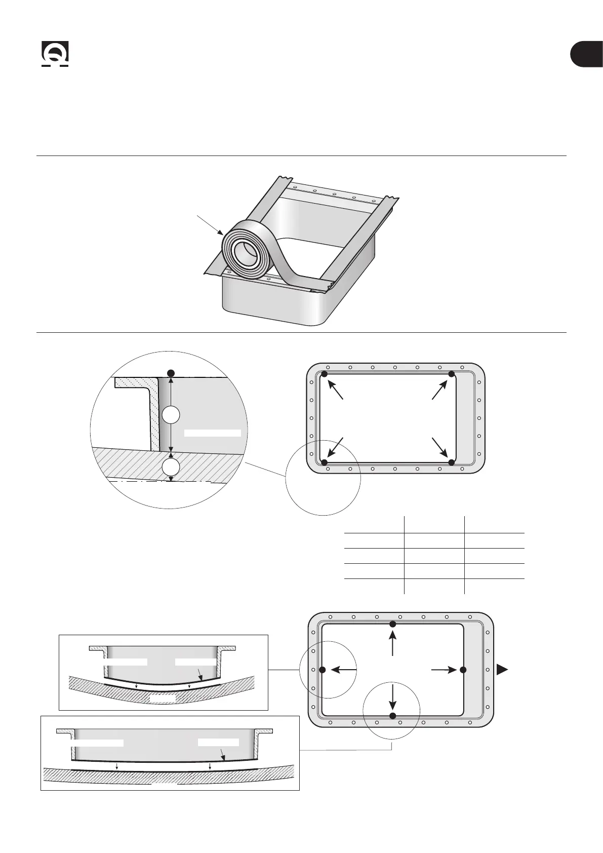
• Protect the seal seat with gummed paper tape to prevent it from getting dirty, until the retractable thruster is installed (Fig. 1A).
fIG.1A
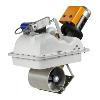
fIG. 1B
• Mark the counter ange with a marker in the four
INDICATED positions of the long sides (Fig.1b), refer to the
table:
HULL
BOW
HULL
COUNTER FLANGE
COUNTER FLANGE
CUT LINE
CUT LINE
• Shape the central parts of the 4 indicated sides of the counter ange by adapting them to the curve of the hull (g. 1C).
h HT
Ø140 37-57mm 30mm
Ø185 60-65mm 35mm
Ø250 65-80mm 40mm
Ø300 110-120mm 40mm
COUNTER FLANGE
GUMMED
PAPER TAPE
COUNTER FLANGE
HULL
COUNTER FLANGE