EN
BTR Series
BTR Series
QUICK BTR Series INSTALLATION AND USER’S MANUAL - REV 001C
6
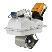
2.0 - Standard supply and material included in the package
• Retractable thruster
• O-ring
• Hinge
• Hatch bracket
• Steel wire rope
• Installation and user’s manual
• Warranty conditions
2.1 - Tools required for installation
BTR 140 • Phillips screwdriver
• Wire cutters
• Drill and drill bit Ø 8.5 mm
• Allen wrench: 2.5 mm
• Fork wrench: 8 mm and 13 mm
BTR 185 • Phillips screwdriver
• Wire cutters
• Drill and drill bit Ø 8.5 mm
• Allen wrench: 2.5 mm
• Fork wrench: 8 mm and 13 mm
BTR 250 • Phillips screwdriver
• Wire cutters
• Drill and drill bit Ø 8.5 mm
• Allen wrench: 2.5 mm and 10 mm
• Fork wrench: 8 mm, 13 mm and 17 mm
BTR 300 • Phillips screwdriver
• Wire cutters
• Drill and drill bit Ø 8.5 mm
• Allen wrench: 2.5 mm and 10 mm
• Fork wrench: 8 mm, 13 mm and 17 mm
2.2 - Recommended Quick
®
accessories not included
• TCD thruster controls
• TSC integrated line switch control
• TMS line switch
• PSS parallel battery switch
• TFH Fuse holder
2 - Supply and equipment
BEFORE USING THE PRODUCT, PLEASE READ THIS USER’S MANUAL CAREFULLY. IF IN DOUBT, PLEASE CONSULT YOUR QUICK® DEALER.
3.0 - Important notes
This manual features Warning and/or Caution symbols that are important for safety.
Please follow the instructions provided.
Warning symbol indicating
dangerous situations.
Caution symbol to prevent direct or
indirect damage to the product.
This manual provides boat manufacturers and nautical equipment installers with instructions on how to assemble the specied
Quick® product and operate it correctly.
3 - Introduction