7
EN
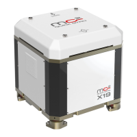
INSTALLATION AND USE MANUAL QUICK MC² X3_DC REV001A
INDEX
Standard equipment and required accessories Pag. 10
Premise Pag. 4
Stabilization principles Pag. 4
The core of boat's stability concept Pag. 4
The centre of thrust Pag. 4
How a quick gyro stabilizer made Pag. 4
The concept of onboard comfort Pag. 4
1 - Information about the product Pag. 8
1.0 - Description Pag. 8
1.1 - Technical data Pag. 8
1.2 - Dimensions Pag. 9
1.3 - Dimensions with base plate (optional) Pag. 9
2 - Supplied parts Pag. 11
2.0 - Package contains the following parts Pag. 11
2.1 - Required accessory, not supplied with the stabilizer Pag. 11
2.2 - Required components, not supplied with the stabilizer Pag. 11
2.3 - Tools needed for installation Pag. 11
3 - Introduction Pag. 12
3.0 - General information Pag. 12
3.1 - Preliminary technical checks Pag. 12
4 - Safety Pag. 13
4.0 - Precautions Pag. 13
4.1 - Warnings Pag. 13
4.2 - Personal protection equipment (PPE) Pag. 14
4.3 - Stickers/labels on the stabilizer Pag. 14
4.4 - Cases Pag. 15
4.5 - Flywheel Rotation Pag. 15
4.6 - Air output Pag. 15
5 - Handling and Transportation Pag. 15
5.0 - General instructions and precautions Pag. 16
5.1 - Crate removal Pag. 16
5.2 - Lifting the stabilizer Pag. 17
6 - Housing Pag. 18
6.0 - Structure and housing analysis Pag. 18
6.1 - Environmental requirements Pag. 18
6.2 - Water line Pag. 18
6.3 - Installing a single stabilizer Pag. 19
6.4 - Installation of multiple units on the same boat Pag. 20
7 - Installation procedures Pag. 21
7.0 - Support structure Pag. 21
7.1 - Types of Underbody Pag. 21
7.2 - Warnings Pag. 21
7.3 - Planarity of installation Pag. 22
7.4 - Stabilizer securing Pag. 23
7.5 - Stabilizer securing with base plate (optional) Pag. 24
7.6 - Fiberglass Support - Example 1 Pag. 25
7.7 - Fiberglass Support - Example 2 Pag. 26
7.8 - Brachet - Example 3 Pag. 27
7.9 - Brachet - Example 4 Pag. 28
8 - Electrical connection Pag. 29
8.0 - Connection system devices Pag. 29
8.1 - Devices dimensions Pag. 29
8.2 - Connection diagram Pag. 30
9 - Start-up Pag. 31
9.0 - Introduction Pag. 31
9.1 - Start-up instructions Pag. 31
10 - Maintenance Pag. 31
10.0 - Introduction Pag. 31
10.1 - Warnings Pag. 31
10.2 - Periodic maintenance Pag. 32
10.3 - Annual maintenance Pag. 33
10.4 - External Cleaning Pag. 33
11 - Scrapping and Disposing Pag. 34
11.0 - Scrapping Pag. 34
11.1 - Disposing Pag. 35
12 - Accessories Pag. 36
Remote Control Pag. 36
Remote Control Accessories Pag. 36