Do you have a question about the Quick MC2 Series and is the answer not in the manual?
Explains the fundamental requirement for boat stability, relating center of gravity to metacenter.
Discusses the movement of the center of thrust during rolling and defines the metacentric height (GM).
Details the mechanical principle of a gyro stabilizer, explaining the gyroscopic effect and stabilizing torque.
Explains how onboard comfort is affected by motion sickness and the role of accelerations and rolling motion.
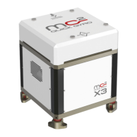
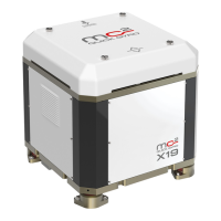
Introduces the MC² series, highlighting its competitive performance, safety, comfort, and high performances.
Lists key features of the MC² stabilizer, including performance, design, flexibility, and protection systems.
Provides detailed technical specifications such as rated speed, angular momentum, output torque, and power requirements.
Shows the physical dimensions of the stabilizer unit without the optional base plate.
Displays the physical dimensions of the stabilizer unit when fitted with the optional base plate.
Lists the components included in the stabilizer's packaging for standard installation.
Describes the RC Remote Control MC² accessory for monitoring and controlling the stabilizer.
Details all parts provided with the MC²X3 Quick gyro stabilizer for installation.
Lists essential accessories and materials that are not included in the stabilizer's packaging.
Identifies necessary components, such as a differential circuit breaker, that must be sourced separately.
Lists the tools required for the proper installation of the gyro stabilizer.
Provides general guidance and responsibilities for installers regarding stabilizer installation and commissioning.
Outlines essential checks to ensure the boat structure can withstand the loads generated by the gyroscope.
Lists general safety precautions to be followed during handling, installation, and operation of the stabilizer.
Highlights critical warnings related to power supply, operation speed, and touching the running stabilizer.
Specifies the required personal protective equipment for installation and maintenance personnel.
Explains the meaning of various danger and caution labels applied to the stabilizer.
Emphasizes the importance of not removing the stabilizer's protective covers.
Details the direction of flywheel rotation and its indication on the stabilizer cover.
Notes that a label indicates the stabilizer's air outlet area during operation.
Provides instructions for safe handling and transportation, emphasizing qualified personnel and caution.
Step-by-step guide on how to safely remove the stabilizer from its shipping crate.
Illustrates the correct method for lifting the stabilizer using straps and avoiding improper lifting techniques.
Stresses the need to ensure the boat structure can support gyroscope loads and advises consulting experts if needed.
Recommends installing the stabilizer in a dry, ventilated place and notes its noise level.
Specifies the allowed inclination of the stabilizer relative to the boat's water line.
Provides guidance on selecting the location and orientation for installing a single stabilizer unit.
Offers recommendations for installing multiple stabilizers on the same boat, including flywheel rotation direction.
Details requirements for the mounting structure, emphasizing certified installers and load analysis.
Discusses installation considerations for fiberglass, aluminum alloy/steel, and wood hulls.
Warns about preventing debris ingress and the correct orientation of the stabilizer relative to the boat's axis.
Specifies the required planarity and tolerance values for stabilizer installation, with or without a base plate.
Explains the process of positioning and securing the stabilizer using a drilling template and specified screws/torque.
Details the procedure for securing the stabilizer using the optional base plate when direct access is limited.
Illustrates a fiberglass support structure with brass plates for hulls with sufficient stringer spacing.
Shows a fiberglass support structure with brass plates for hulls with insufficient stringer spacing.
Demonstrates a bracket-based support structure for a hull with adequate space between stringers.
Presents a bracket-based support structure for a hull with limited space between longitudinal stringers.
Introduces the RC Remote Control MC² touch as the dashboard device for monitoring and control.
Provides the physical dimensions and specifications for the RC Remote Control MC² touch device.
Illustrates the electrical wiring and connection points for the stabilizer, remote control, and power supply.
Introduces the section on the first start-up and commissioning of the stabilizer.
Guides the user on the sequence of operations for the initial start-up of the stabilizer.
States that stabilizers are built with marine-resistant materials and require mandatory maintenance.
Lists critical warnings regarding power disconnection, flywheel stopping, and warranty voidance during maintenance.
Details periodic maintenance requirements, including frequency and contact for authorized service.
Outlines the annual maintenance tasks, including checks for corrosion, electrical connections, and fixing tightness.
Provides instructions for cleaning the stabilizer's exterior using a soft cloth and water.
Describes safety measures and procedures for scrapping the machine, considering logistics and environment.
Provides rules for disposing of machine components, including separation of materials and hazardous waste.
Lists the RC Remote Control unit with its description and code.
Lists accessories related to the remote control, such as connector cables and terminators.
Lists components for electrical protection, including fuses and circuit breakers with their codes.
| Brand | Quick |
|---|---|
| Model | MC2 Series |
| Category | Marine Equipment |
| Language | English |