18
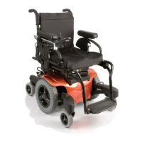
Holding the connector housing, firmly push the connector into its mate until you can
no longer see the yellow plastic. The connectors are secured using a friction system.
To disconnect the communication cables:
Holding the connector housing firmly, pull the connectors apart.
NOTE
– Do not hold or pull on the cable. Always grip the connector when connecting and
disconnecting.
When the control system is first switched on after a connection, or system component
change, the timer will be displayed while the system checks itself. Then the re-start icon will
be displayed. Switch the control system off and on again to operate,
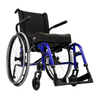
C. RNET JOYSTICKS
Controls:
LED, Color Display, and Advanced Joystick
Joystick key:
LCD Screen (B), Paddle Switch (Left and Right) (C), External Profile Jack (D),
External On/Off Switch Jack (E).
WARNING
Cleaning the LCD screen (B)
1.
ALWAYS
use a soft, clean, lint free, dry cloth
2. To clean fingerprints and greasy smudges off of your LCD screen use a screen clean-
ing solution that is designed for LCD screens (Non-ammonia based). Put a small
amount of the solution on a clean, lint free, dry cloth and rub the screen gently.
3.
NEVER
use any type of windex cleaner, soap, scouring powder, or any cleanser with
solvents such as alcohol, benzene, ammonia, or paint thinner.
4.
NEVER
use abrasive pads or paper towels. If you do, you can scratch the screen or
strip the anti-glare coating off of the screen and cause permanent damage to the
Joystick screen.
A. CONTROLS
15
Omni2 Input Display
is a universal specialty controls interface that accepts signals from many different types of
SIDs and translates them into commands compatible with the PG Drives Technology RNET
control system.
B.
CONNECTORS
16
17
M
a
ti
ng
C
o
nne
c
to
r
s
To
connect
the
communication
cables (A):
18
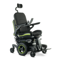
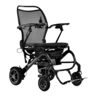
IX. CONTROLS, JOYSTICKS & OPERATING GUIDES
Power
Module
JOYSTICK
17
16
18
Advanced Joystick shown
C
D
E
B
A
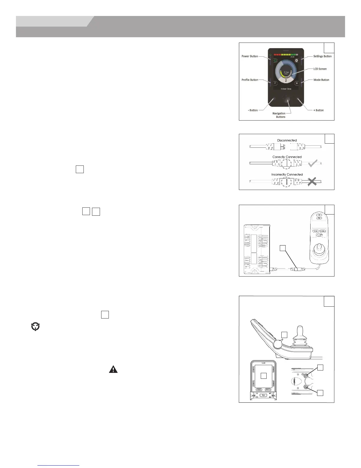
Profiles and modes explained: The operation of the RNET system is based around the
concept of Profiles and Modes.
A Profile is a collection of programmable parameters that affect the operation and
performance of the wheelchair. It is typical to have 5 Profiles, each set-up to give a different
driving performance. For example, Profile 1 may have very slow settings for speeds and
accelerations, while Profiles 2 through to 5 would have progressively faster settings. In this
way, the user can change the performance of the wheelchair by selecting the appropriate
Profile with the Profile Button on the JSM. Although Profiles are used mainly to change
driving performance, they can also contain parameters for other functions, such as seating
control.
A Mode reflects the actual operation that occurs as a result of a joystick command. Typical
examples are Drive Mode, Seating Control Mode and Bluetooth Mode. The user can select
the required Mode with the Mode Button on the JSM. Note, it will only be possible to select
a Mode if there is a Module that will support that Mode connected into the system. For
example, if there is no Mouse Module connected, then the user will not be able to select
that Mode.
15