27
QM-710/715HD/720
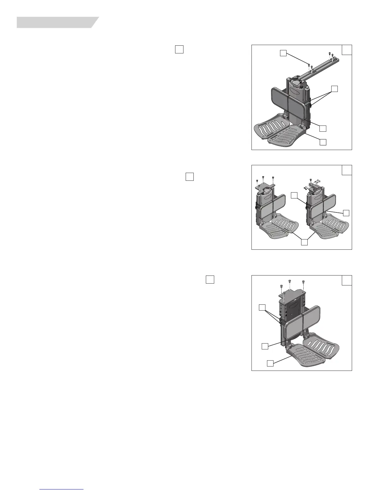
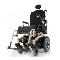
H. POWER CENTER MOUNT FOOTREST (ASAP)
1. Footrest Depth Adjustment (Not recommended)
a. Remove the hardware(A) from the support frame tubes.
b. Move the footrest assembly forward or back for depth adjustments
c. Insert the hardware to lock the adjustment in place.
d. Re-tighten all hardware.
2. Calfpad height, depth and angle adjustment
a. Using a 5mm hex key, loosen both screws(B) and move the calfpad to the desired
setting.
b. Adjust both sides equally in most cases.
c. Re-tighten the hardware.
3. Footplate Height Adjustment
a. The footplates(C) can be raised or lowered
b. Using a 5mm hex key, loosen the screws (D) holding the upper footplate mounting
bracket, and move the footplates up or down to set the correct height.
c. Re-tighten the hardware to hold the adjustment in place.
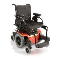
I. POWER CENTER MOUNT FOOTREST (RECLINE)
1 Calfpad height, depth, and angle adjustment
a. Using a 5mm hex key, loosen both screws(B) and move the calfpad the the desired
support distance.
b. Adjust both sides equally in most cases.
c. Re-tighten the hardware.
2. Powered Footplate Height Adjustment
a. Using a 5mm hex key, loosen the screws (D) holding the upper footplate mounting
bracket, and move the footplates up or down to set the correct height.
b. Move the footplates (C) up or down to set the correct height.
c. Re-tighten the hardware to hold the adjustment in place.
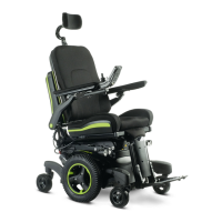
J FIXED CENTER MOUNT FOOTREST (POWER RECLINE)
1 Calfpad height, depth, and angle adjustment
a. Using a 5mm hex key, loosen both screws(B) and move the calfpad to the desired
support distance.
b. Adjust both sides equally in most cases.
c. Re-tighten the hardware.
2. Powered Footplate Height A
djustment
a. Using a 5mm hex key, loosen the screws (D) holding the upper footplate mounting
bracket, and move the footplates up or down to set the correct height.
b. Move the footplates (C) up or
down to set the correct height.
c. Re-tighten the hardware to hold the adjustment in place.
51
52
53
XI. DEALER SERVICE AND ADJUSTMENT
53
51
A
B
C
52
B
C
B
D
D
C
D