14 FOM5-00AM-DES-RNN5 V1.0 / 10.03.2015
Technical description
Network nodes Q node 5 receive and process data from consumption metering devices (maximum 500) within the Q AMR system. Several
network nodes (maximum twelve) form a network. There are different types of network node for the different application cases. All types can
be combined with one another in a network.
Technical data Q node 5
CE conformity
Protection rating IP 20
Protection class II
Electromagnetic compatibility
Interference resistance:
Emitted interference:
Security of IT equipment
EN 301 489
EN 300 220-1
EN 60950
Rated voltage DC 3.6 V
Service life
Main battery (with factory settings)
Backup battery
> 5 years
> 10 years
Ambient conditions
during transport in non-ventilated containers
in ventilated containers
Relative air humidity
-25…+70 °C
-25…+40°C
max. 95% at 40°C
during storage
Relative air humidity
-5…+45 °C
max. 95%
during operation
Relative air humidity
…+55 °C
max. 95%
Weight gross
net
0,760 kg
0,648 kg
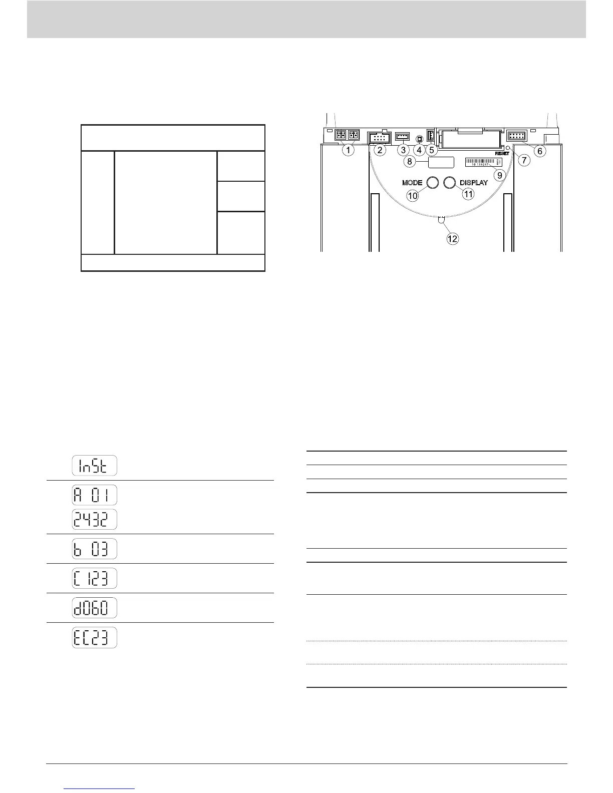
Display levels
-
Current
operating mode (Mode)
A
Alternating Q node 5 number (primary
address) and network number
B
Number of Q node 5 in the network
C
Number of consumption metering
devices in the network
D
Remaining capacity of the main bat-
tery of the Q node 5 in percent
E
Fault codes (three groups)
Components Q node 5
The network node Q node 5 is made up of the following components:
Power supply:
Battery
Transmitter / receiver for
Network
Memory
500 measuring devices
M-Bus
(Slave)
IrDA
(optical)
Backup battery
Transmitter and receiver are used for recording the data from con-
sumption metering devices and forwarding these to other network
nodes in the same network. The data memory contains the meas-
uring data from the consumption metering devices. It is protected
against temporary power failure, for instance during replacement of
the main battery, by the backup battery. Local network readout can
take place via the M-Bus interface (an M-Bus load).
Parts and operating elements
(1) Plug connector for M-Bus
service connection
(2) Plug connector for extension
module
(3) Plug connector for voltage
supply DC 3.6 V
(4) LED for network voltage
display with external supply
(only lit during mains supply)
(5) Plug connector for backup
battery DC 3.6 V
(6) Connector outlet
(7) Reset key (recessed)
(8) Display
(9) Serial number
(10) Operating mode key
(MODE, red)
(11) Display switchover key
(DISPLAY, blue)
(12) IrDA interface (opti-
cal)
Keys
The network node has 3 keys with the following functions:
DISPLAY Key (10) for switching over the display and acknowledging faults.
MODE Key (9) for switching installation mode on or off. If an extended mode is active, this key is pressed to return to the standard mode.
RESET Recessed key (7) for triggering a network reset (interruption of all connections between the network nodes).
 Loading...