Do you have a question about the Quoizel WVR8407A and is the answer not in the manual?
Turn off electricity, consult electrician if unsure, read instructions completely.
Identify parts, check contents, disconnect power before bulb replacement.
Insert glass panel into the top edge slot and secure it with the tabs.
Attach crossbar assembly to outlet box using mounting screws and supply wires.
Connect ground wire to green ground screw, then join other wires using connectors.
Position backplate and fixture body onto crossbar assembly, secure with mounting balls.
Insert bulb, then apply exterior grade caulk around backplate top and sides.
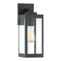
This document provides installation instructions for the Quoizel WVR8407A outdoor wall lantern, an artisan-designed lighting fixture. The guide covers the entire process from unboxing and preparation to final assembly, wiring, bulb installation, and sealing.
The Quoizel WVR8407A is an outdoor wall lantern designed to provide illumination for exterior spaces. It features a single light source and is intended for permanent installation on an exterior wall, connecting to a standard electrical outlet box. The fixture's design incorporates a glass panel and an antique brass finish, suggesting a classic or vintage aesthetic. The installation process emphasizes secure mounting and proper sealing to protect against moisture, making it suitable for outdoor use.
The installation is estimated to take 20-30 minutes and requires basic tools such as screwdrivers (flathead and Phillips), pliers, wire cutters, wire strippers, electrical tape, and safety glasses.
| Brand | Quoizel |
|---|---|
| Model | WVR8407A |
| Category | Outdoor Light |
| Language | English |