Bubble‐Up®JrInteractive™RadonRemovalSystem
26
TECHNICALDATA
FlowRate…………………………………...SeePressureflowchartbelow
Powersource………………………….115VoltAC,60Hz,singlephase
HPrating…………………………………………..………………1.5HP115
volt
OperatingPressureRange………………………………………….0–75PSI
MaximumAllowablePressure………………………………………...80PSI
MaximumLiquidTemperature…………………………………………100°F
Connection…………………….1”SCD80unioninlet,1/2”PEXoutlet
ProtectionLevel…….………………ULListedPressureSwitch&
cords
C.INSTALLATION
1. Useonly115voltoutletfortheBubble‐Upmechanicalpumpcontrol.
2. Thebottom1”schedule80unionandtop½”PEXfittingsaretobewatertightandsecure.
3. Checkthatthepumpisprimedbeforepl uggingintheBubble‐Upmechanicalpumpcontrol.
4. TheBubble
‐Upmechanicalpumpcontrolissuppliedwith115voltelectricalcords.Conne ctthepump’smale
powerplugintotheBubble‐Upmechanicalpumpcontrolfemalecord.
5. Tostartthepump,refertoOPERATIONbelow.
6. Thepressureswitchfactorysetattoturnthepumponat45PSI.
Tosetpressureswitchforproperoperation
seeinstructionsabove.
WARNING!UnplugtheBubble‐Upmechanicalpumpcontrolbeforeremovingthepressureswitchcover.
7. AlwaysusethebladdertankprovidedwiththeBubbleUp.Thecorrectpre‐chargeairpressureinthetankis40
psi.
D.OPERATION
Seesettingpressureswitchabove.TheBubble‐Upmechanicalpumpcontrolstartsthepumpwhenthepressuredrops
to45PSI.Thepumpwillrunconstantwhentheflowisgreaterthan½to1GPM.Whenwaterflowfallsbelow½to1
GPM,waterfillstherequiredcycletank
providingaminimumruntimebeforethepumpisshutoff.
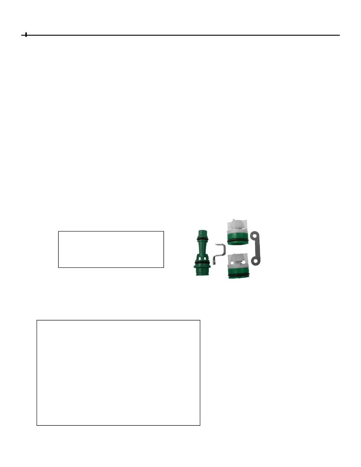
Internalpartsinclude:2‐CheckValves,
aNozzleandThroatAssemblywith
retainer,DoubleCheckValveand
NozzleRetainerand3screws.