Instruction Reference Manual 85
Description
Rotates to the left the data whose address is:
• the data in word register HL, or
• the sum of the data in index register IX and a displacement d,or
• the sum of the data in index register IY and a displacement d.
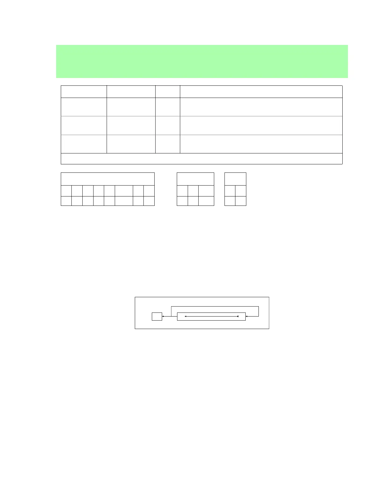
Each bit in the register moves to the next highest-order bit position (bit 0 moves to bit 1, etc.) while bit 7
moves to both bit 0 and the CF. See Figure 2 below.
Example
If the HL contains 0x4545, the byte in the memory location 0x4545 is 0110 1010, and the CF is set, then after
the execution of the operation:
RLC (HL)
the byte in memory location 0x4545 will contain 1101 0100 and the CF will be reset.
RLC (HL)
RLC (IX+d)
RLC (IY+d)
Opcode Instruction Clk Operation
CB 06 RLC (HL)
10*
(HL) = {(HL)[6,0],(HL)[7]};
CF = (HL)[7]
DD CB d 06 RLC (IX+d)
13**
(IX + d) = {(IX + d)[6,0],(IX + d)[7]};
CF = (IX+d)[7]
FD CB d 06 RLC (IY+d)
13**
(IY + d) = {(IY + d)[6,0],(IY + d)[7]};
CF = (IY + d)[7]
Clk: Clocking: *10 (2,2,1,2,3) **13 (2,2,2,2,2,3)
Flags ALTD I/O
S Z L/V C F R SP S D
• • L • • • •
Figure 2: The bit logic of the RLC instruction.
CF
7
0