Dynalyzer – Digital Display/Printer OPERATION MANUAL
9
Operation
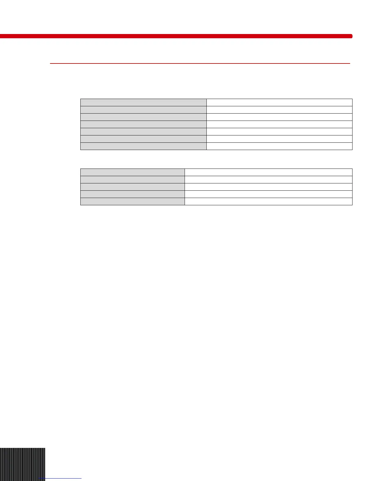
Specifications
Printer
Characters
116 characters, 5 x 7 font, 24 characters per line
Data Per Line
24 characters per line
Duty Cycle
Continuous
Print Rate
1.7 lines per second
Input Buffer
6900 characters
Paper Advance
Paper feed switch
Paper Supply
Plain paper, 2-1/4”W x 1,6” OD
RS-23-2 Connector
Connector
DB-9 (9-pin)
Baud Rate
2400
Data Bits
8
Stop Bits
1
Parity
None
Initial Setup and Self Test
1. Determine input line voltage (104-125 or 220-240 VAC) and ensure that input power connector
is properly set. See Figure 5.
2. Plug the Digital Display power cord into the same source of power used for the High Voltage
Unit. This should be the same for AC branch circuit and preferably the same receptacle. Be
sure the power source is equipped with an approved earth ground.
3. Place the POWER switch in ON position or depress RESET if already ON. All displays should
read zero.
4. Verify correct operation by placing the Digital Display in the TEST mode. To use the TEST
mode:
a. Turn Voltage Display Select switch to A or C.
b. Turn mA/mAs Display switch to mA.
c. Turn TRIGGER SOURCE switch to kVp; kV Delay and Window Delay fully
counterclockwise (OFF).
5. Turn PROCEDURE switch to TEST position. After about 10 seconds the self testing cycle is
complete. No information should be visible in the Percent/Preset window. The A + C window
should indicate 10.00 ± 0.3. The mA window should read “5226”. If a three digit Error Code
(other than 903) appears in the Percent/Preset window, this is an indication of a malfunction or
improper control setting.
 Loading...