Dynalyzer – Digital Display/Printer OPERATION MANUAL
10
NOTE: Background nulling will provide an incremental improvement in mR accuracy and is
only useful when exposure rates below 50mR/sec are encountered.
6. Connect the twenty-foot cable (supplied) between the High Voltage Unit and the Digital
Display. This cable is connected to the H.V. Unit connector on the Digital Display, and the
Digital Display connector on the High Voltage Unit. Both ends are identical. The connector
locks with a half turn.
7. Connect an oscilloscope, if desired, to oscilloscope outputs on the Digital Display. Plug the
scope power cord into the same grounded receptacle as the Display and High Voltage Unit.
The A + C output is 1 volt per 20 kV; the mA output will be 20 mV per mA if FLUORO is
selected, or 1 mV per mA if RAD is selected at the High Voltage Unit.
8. Reset the PROCEDURE switch on the Digital Display to NORMAL. The unit should again
display 0’s.
CAUTION: As 5 foot long high voltage cables are normally used to connect the Dynalyzer
III High Voltage Unit to the x-ray tube (necessitating that the HVU be placed
on the table) the possibility exists that the HVU may be inadvertently placed in
the primary beam. If this occurs, the SF6 gas used to insulate the internal
components in the tank section of the HVU may become sufficiently ionized to
cause gross measurement errors, e.g., 20 to 30 kV. In order to guard against
this possibility, the user must be careful to angle the tube away from the HVU
or close the collimator shutters.
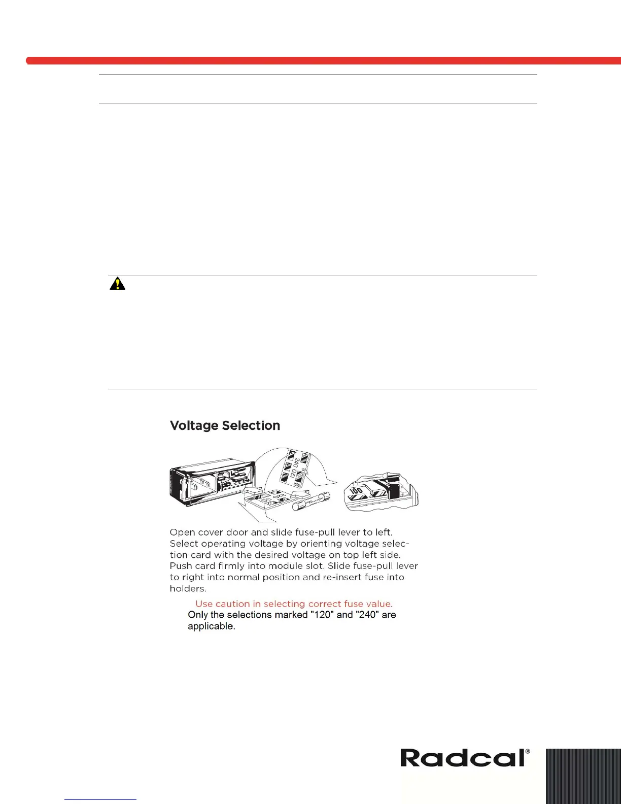
Figure 5: Voltage Selection
Triggering Sources
There are several different methods of starting or triggering the Dynalyzer III Display measurement
and analysis functions for an x-ray exposure. The TRIGGER SOURCE switch is used to determine
which trigger source is to be used.