Dynalyzer – Digital Display/Printer OPERATION MANUAL
16
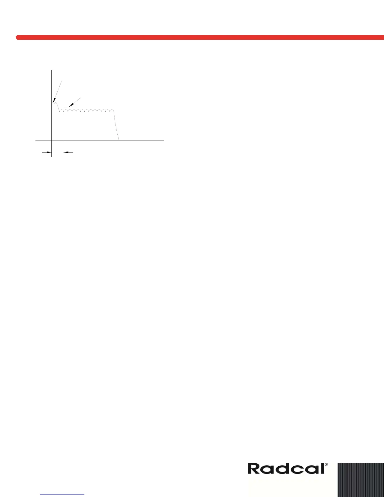
Figure 11: Use of kV Delay to Compensate for kV Overshoot
Fluoroscopic Current Measurements (0-20 mA)
Dual ranging mA has been provided on the Dynalyzer III High Voltage Unit to improve low mA
accuracy. Unless the High Voltage Unit is zeroed while connected to the Display, errors can be
introduced. The “mA zero” control is a screwdriver potentiometer adjustment requiring slight motion
to trip the expected drift of several millivolts. This zero is temperature sensitive. As the system
reaches thermal equilibrium, the zero on the High Voltage Unit must be readjusted if it drifts.
The mA zero setting, if slightly above true zero, may be verified by triggering the Digital Display on
AUTO with the fluoroscopic current set to zero (generator off). Any mA reading on the display
would represent the combined offset error of the High Voltage Unit and the Display Converter
Circuit (which should not be field adjusted). This value should be subtracted from the reading
during operation.
The dual range scale conversion factors of 1 millivolt per milliampere for radiographic and 20
mV/mA for fluoroscopic measurements are controlled by a switch on the High Voltage Unit. If AC
noise is introduced on the signal line, the temperature-sensitive drift of the circuitry will not be
averaged out, therefore care in grounding must be taken (the HVU and Display should be plugged
into the same receptacle with a good earth ground.) A differential input has been provided on the
mA line circuitry so that common mode and ground noise is reduced. A separate return is provided
for the mA signal into the Dynalyzer III High Voltage Unit.
Window Delay Mode Operation
A new feature has been added to the Dynalyzer III which enables viewing any 20 msec part of the
first second of an exposure.
To use this function, the WINDOW DELAY control must be turned ON past its minimum delay time
of 50 msec, at which point the associated LED lights to indicate that the Window Mode is selected.
The length of window delay is displayed in the MSEC exposure time window. The MANUAL
TRIGGER, CLEAR READING, or RESET pushbuttons must be momentarily depressed.
In a falling load type generator, with several current values and time intervals between these
values, the window delay function is needed to set the kVp and emission at each step.
kV OVERSHOOT
kV MEASURED
kV DELAY SET
FOR 20 ms
 Loading...