Dynalyzer – Digital Display/Printer OPERATION MANUAL
8
PERCENT/PRESET
MODE
TRIGGER
FIL. AMPS
DYNALYZER III - DIGITAL DISPLAY
1000 MSECOFF
MSEC.
MAS
MA
CATHODE
A + C
ANODE
WINDOW DELAY
0
20MS
KV DELAY
TRIGGER LEVEL
I
N
C
R
E
A
S
E
ERROR
TEST
NORMAL
TRIGGER SOURCE
EXT
AUTO
KVP
MA
PROCEDURE
COEFF
VAR
PRESET
PERCENT
POWER
R
RESET
OFF ON
RECALL
EXPOSURE
EXT
MA
KVP
PRINTER
OFF
AUTO
PRINT
NUMBER
EXPOSURE
TRIGGER
MANUAL
READING
CLEAR
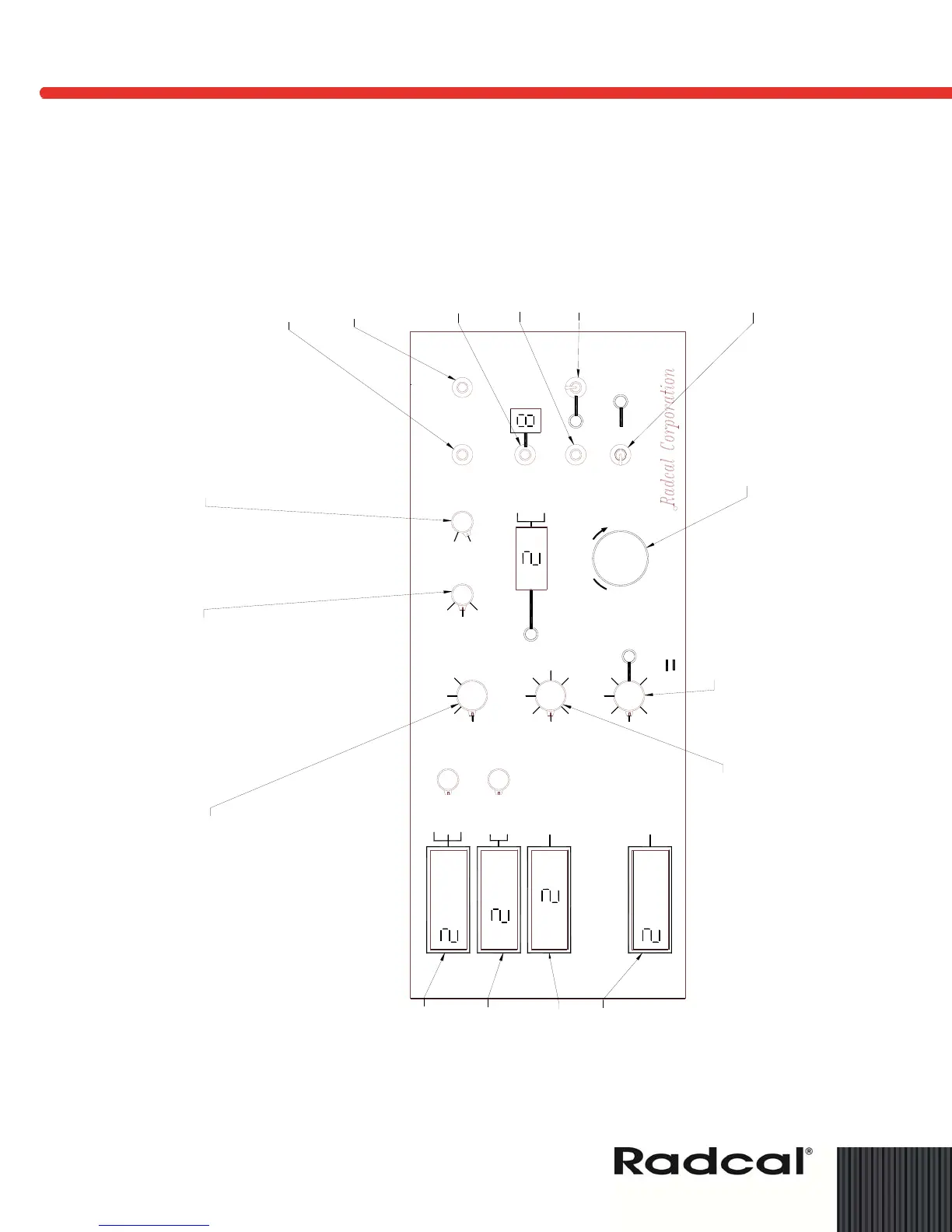
TRIGGER LEVEL - Multi-turn poteneiometer
allows user to dial in PRE-SET or PERCENT
trigger levels prior to exposure. The
trigger level selected is read at
Preset/Percent display. Trigger level is
only applicable when kVp, mA or EXT
trigger source is selected.
WINDOW DISPLAY - Single turn potentiometer.
Upon acknowledgement of system trigger,
delays reading of all data excluding time
by a preset time interval. Window delay time
can be from 25 to 1,000 mS. This mode is
indicated by adjacent LED indicator. To
enable this mode, control can be set to
desired delay period and either MANUAL
TRIGGER, CLEAR READING or RESET
push-buttons momentarily depressed.
TRIGGER SOURCE - Five- Position
switch for trigger source selection.
EXT - This switch position allows
system to trigger from an external
source.
AUTO - This position allows system
to trigger from the internal clock.
(Internal update rate approximately
1.0 sec.)
mA - This position allows system
to trigger from mA source.
kVp - This position allows system
to trigger from kVp source.
TRIGGER MODE - Two-position
switch, user selectable for Trigger
Mode of operation.
PERCENT - This trigger mode of
operation is used in conjunction
with the "Trigger Level" potentiometer.
The user presets the trigger level
prior to exposure by dialing in
a trigger level of typically 10% of
pulse height for single-phase and
75% for three-phase.
PRESET - This trigger mode of
operation is also used in conjunc-
tion with "Trigger Level" potentio-
meter. The user presets the trigger
level prior to exposure by dialing
in an absolute kVp or mA value.
PROCEDURE - Three-position switch
for Coefficient of Variation measurement.
System Test and Normal.
COEFF. VAR. - Calculates co-
efficient of variation for up to the
last 10 exposures and outputs the
result to the corresponding display.
The FIL, AMPS, LINE N/L and LINE
functions are not applicable in this
mode.
TEST - In this mode, the system
performs a test of its own analog
and digital circuitry and allows
background radiation nulling for
the radiation probe. Upon error
detection, system signals an error
code and lights the "ERROR" LED
indicator.
kV DELAY - Single turn potentiometer.
Upon acknowledgement of system trigger,
this potentiometer delays system reading
of kV for a preset time interval, allowing
only the trailing portion of the pulse to affect
the reading. kV reading can be delayed
up to 20 mS.
used.
position ind EXT Trigger Inputs not
that the trigger source be in EXT
operation is used, it is recommended
*When MAN TRIGGER mode of
CLR READING - This push-button,
when depressed, clears out the
current exposure data corresponding
to the EXPOSURE NUMBER
EXPOSURE RECALL - This push-button,
when depressed, is used to recall each
of the 9 (or fewer) previous exposures.
Depressing this switch decrements the
Exposure Number and displays past
exposure data.
RESET - This push-button, when
depressed, clears all registers and
re-initializes system for the start
of the next exposure sequence.
PRINTER - This multi-function
switch is used to control printer
operations. A LED indicator, when
lit, signifies printer ON.
PRINT - This is a momentary (hand
held) switch position. When in upper
position the most current exposure
data is printed.
OFF - Disables printer from printing.
LED indicator OFF.
AUTO - When depressed, the switch
is locked in an "ON" position. The
system automatically prints
exposure data after each exposure.
POWER - When in the "ON" position
the power ON/OFF LED indicator
should be lit.
*MANUAL TRIGGER - This push-button,
when dwpressed, activates readouts
of standby FIL/AMPS and Line Volts, kVp,
mA or mAs, and mR. If printer is in AUTO
position the data read is routed to the
printer.
MSEC - Measures exposure time.
MA/MAS DISPLAY - Measures
average current or current integrated
over time. Values for both positions
are stored and can be selectively
displayed after the exposure.
kVp DISPLAY - Measures kilovolts
peak for Anode, Cathode or Anode
+ Cathode. Reading deisred must
be selected prior to exposure.
FIL, AMPS. Measures AC rms
current during exposure.
To measure standby filament
current prior to exposure, depress
MANUAL TRIGGER.
Figure 4: